Toyota Corolla Forum
Electrical component of Toyota Corolla. Electrical circuits, electrical problems, search for solutions. Alexey 178 Messages: 3 Registered: Feb 11, 2013, 11:58 pm
#1
Post by Alexey 178 » 12 Feb 2013, 00:07
Hi all. I have a 2007 Corolla. The ABS error came on, I did some diagnostics and it showed that the right rear sensor was damaged! I changed the sensor assembly with the hub and changed the wire that goes to the sensor accordingly. We did the diagnostics, and nothing works, the error is on again!!! In short, I was tired of visiting the service center.
The official dealer just said some nonsense and wanted to scam me out of money, others said leave the car all day and we’ll look for the problem. I'm not a sucker and I won't leave my car all day. The electrician said that the hub was probably made in China, but I bought it through a friend who sells spare parts, and the box said Japan.
Has anyone encountered this problem???
validuserHonored Korollov Messages: 6048 Registered: 15 Jan 2013, 14:17 Car: Mazda CX-5 Location: Saratov Thanked: 72 times Thanked: 131 times
#2
Post by validuser » Feb 13, 2013, 10:49 pm
Question: Which wire did you change? Coming from where and where? From block to hub? First, it was necessary to ring the sensor in the hub and compare it with a similar one on the other side, for example, or with any other.
And the wire had to be tested for a break going from the sensor to the ABS unit.
And if they didn’t call, then you take a multimeter (tester in Russian) and look directly at the sensor at the moment the ignition is turned on, there should be power there, and both on the left and on the right are the same, if one of them is not, then this wire is broken.
48RONINModerator Messages: 2629 Registered: 07 Jan 2013, 17:42 Car: May 2007
1.6 manual transmission 17 Location: Lipetsk Thanked: 39 times Thanked: 65 times
#3
Post by 48RONIN » Feb 14, 2013, 10:43 pm
Are there any traces left from such diagnostics, an error code or anything else? 48RONINModerator Messages: 2629 Registered: 07 Jan 2013, 17:42 Car: May 2007
1.6 manual transmission 17 Location: Lipetsk Thanked: 39 times Thanked: 65 once
#5
Post by 48RONIN » Feb 15, 2013, 10:56 pm
I studied the issue a little and came to the conclusion that the problem of the ABS electronic control unit can be assessed independently using the attachment below. The test is carried out on a stationary car. Reading fault codes* can be done using the ABS indicator on the instrument panel by short-circuiting terminals “13” and “4” of the connector in the car interior:
ABS check.png
*- codes can be posted if necessary “31″ – malfunction of the front right wheel rotation sensor; “32″ – malfunction of the front left wheel rotation sensor; “33″ – malfunction of the right rear rotation sensor.” 34″ – malfunction of the rear left wheel rotation sensor;
The sensors themselves can be checked by measuring the resistance between the terminals; for working ones it is 1.4-1.8 kOhm.
You do not have the necessary permissions to view the attachments in this message.
mytoyotaClub Archivist Messages: 251 Registered: Jan 26, 2013, 10:13 pm Thanked: 6 times
#6
Post by mytoyota » Feb 15, 2013, 11:01 pm
GroSSHonorary member of the club Messages: 667 Registered: 07 Jan 2013, 19:11 Car: Nissan Qashqai+2 Location: Ryazan, Kolomna MO
#7
Post by GroSS » Feb 15, 2013, 11:04 pm
Most likely the dirt thawed and got into the interior.
The sensor is located in the hub. you can try cleaning it. Try cleaning the contacts in the sensor chip, the contact may be bad
Branch of the forum on social media networks VKontaktemytoyotaArchivarius Club Messages: 251 Registered: 26 Jan 2013, 22:13 Thanked: 6 times
#8
Post by mytoyota » Feb 15, 2013, 11:06 pm
48RONINModerator Messages: 2629 Registered: 07 Jan 2013, 17:42 Car: May 2007
1.6 manual transmission 17 Location: Lipetsk Thanked: 39 times Thanked: 65 times
#9
Post by 48RONIN » Feb 15, 2013, 11:08 pm
– the primer suggests using a screwdriver, with the help of which the latch is apparently bent. Just a caveat: Be careful not to damage the sensor.
You can act according to the technical document, only it starts with the plastic of the gearshift lever.
Removing the rear wheel hub, by the way, there is also confirmation of the top picture for removing the connector.48RONINModerator Messages: 2629 Registered: 07 Jan 2013, 17:42 Car: May 2007
1.6 manual transmission 17 Location: Lipetsk Thanked: 39 times Thanked: 65 times
#10
Post by 48RONIN » Feb 15, 2013, 11:09 pm
This may be why:
Using SST (Tool 09214-76011), a steel plate and a press, install the new speed sensor to the rear wheel hub and bearing assembly.
NOTE: Keep the rear speed sensor away from the magnets.
Do not install the rear speed sensor using a hammer. Make sure that the recording part of the rear speed sensor is free of foreign particles such as iron filings.
Slowly press in the rear speed sensor in a straight line.
It seems simple, but you’ll probably have to install it yourself – there will be problems. So it turns out that it’s easier to assemble.
Vova Messages: 2 Registered: April 8, 2014, 2:17 pm Car: Toyota Corolla E12, 2001
#13
Post by Vova » 09 Apr 2014, 18:03
In general, this is not a rare question - I found many similar ones on the internet, but... not a single specific solution. Maybe someone has already encountered this?
vladimir21-177 Messages: 46 Registered: March 20, 2014, 16:30 Car: Toyota Corolla E150 2007 engine 1.6 124 hp, mobil super3000 5w40/robot gearbox
#14
Post by vladimir21-177 » 09 Apr 2014, 18:25
Otherwise, you won’t find an answer, take it to a service center and let them look at the computer, there is a very strong suspicion that your contact on the sensor has rotted. And this can be treated by replacing the sensor, but the infection comes together with the hub! What's your mileage? In general, cleaning may be enough, but you need to understand which sensor is sick! andromeda1973 Messages: 164 Registered: November 26, 2013, 18:07 Car: Toyota Corolla E 150.1NR-Fe.1.33, mileage 164,000, 2012. Location: Tavda, Sverdlovsk region
#15
Post by andromeda1973 » Apr 09, 2014, 6:29 pm
So you need to look for the reason, what’s wrong
? You need to put a jumper in the diagnostic connector
The purest joy is the schadenfreude we feel when observing the misfortunes of those we envy...
andromeda1973 Messages: 164 Registered: Nov 26, 2013, 6:07 pm Car: Toyota Corolla E 150.1NR-Fe.1.33, mileage 164,000, 2012. Location: Tavda, Sverdlovsk region
#16
Post by andromeda1973 » Apr 09, 2014, 6:33 pm
I don’t know how to copy links, TechDoc V1.0, look it up on the Internet, the whole procedure is written there on how to diagnose the system
The purest joy is the schadenfreude we feel when observing the misfortunes of those we envy...
DyushaHonored Korollovod Messages: 11430 Registered: March 30, 2013, 01:53 pm Car: Corolla, 2011, 4 automatic transmission, 1.6 l petrol diesel, Comfort+, drank more than 9700 l/Ai92, Toebta 0W20 Location: 133, Kovrov Thanks : 7 times Thanked: 24 times
#17
Post by Dyusha » April 10, 2014, 00:07
At the front, you can change the rear sensor only with the hub.
To go to TechDoc, click in my signature on Somewhere here.
Last edited by Dyusha on April 10, 2014, 04:23 pm, edited 1 time in total. Das ist Honorary Korollovod Messages: 5049 Registered: Jan 16, 2013, 09:40 am Car: corolla2007 Thanked: 2 times Thanked: 18 times
#18
Post by Das ist » April 10, 2014, 06:41
ABS fault codes (Toyota)
Read codes (models with DLC3 connector)
– Jumper the “TC” and “CG” terminals of the DLC3 connector. – Turn on the ignition. – After 4 seconds, read the code by the number of flashes of the ABS indicator. – Remove the jumper from terminals “TC” and “CG”. Resetting codes (models with DLC3 connector) – Jumper the “TC” and “CG” terminals of the DLC3 connector. – Turn on the ignition. – Press the brake pedal eight or more times within an interval of three seconds. – The indicator should display the norm code (flashing 2 times per second). – Remove the jumper from terminals “TC” and “CG”. 11 Open circuit in the solenoid valve relay circuit 12 Short circuit in the solenoid valve relay circuit 13 Open circuit in the electric pump relay circuit 14 Short circuit in the electric pump relay circuit 21 Open circuit or short circuit in the front right wheel solenoid valve 22 Open circuit or short circuit in the electric valve m valve of the front left wheel 23 Open circuit or short circuit in the solenoid valve of the rear right (left) wheel 24 Open circuit or short circuit in the solenoid valve of the rear left (right) wheel 31 Malfunction of the front right wheel speed sensor 32 Malfunction of the speed sensor front left wheel 33 Malfunction of the rear right wheel speed sensor 34 Malfunction of the rear left wheel speed sensor 35 Foreign material between the rotor and the front right wheel ABS sensor 36 Foreign material between the rotor and the front left wheel ABS sensor 38 Foreign material between the rotor and the front left wheel rear right ABS sensor 39 Foreign material between the rotor and the rear left ABS sensor 41 Battery voltage too high or too low 43 Malfunction in the deceleration sensor circuit 44 Open or short circuit in the deceleration sensor circuit 49 Open in the brake light switch circuit 51 Electric pump power supply short circuit or open circuit 71 Front right wheel speed sensor signal low 72 Front left wheel speed sensor signal low 73 Right rear wheel speed sensor signal low 74 Rear left wheel speed sensor signal low 74 Low signal level from the rear left wheel speed sensor wheel speed sensor 75 Incorrect signal change from the front right wheel speed sensor 76 Incorrect signal change from the front left wheel speed sensor 77 Incorrect signal change from the rear right wheel speed sensor 78 Incorrect signal change from the rear left wheel speed sensor 79 Malfunction of the deceleration sensor
98 Vacuum sensor in the vacuum brake booster (C1200)
Vova Messages: 2 Registered: April 8, 2014, 2:17 pm Car: Toyota Corolla E12, 2001
#19
Post by Vova » April 10, 2014, 15:59
When checking, the computer seemed to show that the problem (error) was in the deceleration sensor, which is located under the automatic transmission shift lever panel. And this seems to be the problem with ABS. It's real?
vladimir21-177 Messages: 46 Registered: March 20, 2014, 16:30 Car: Toyota Corolla E150 2007 engine 1.6 124 hp, mobil super3000 5w40/robot gearbox
#20
Post by vladimir21-177 » Apr 10, 2014, 4:18 pm
Hmmmm I haven’t heard of such a problem! Usually the classic problem with this error is either the contact is clogged, or the contact is rotten,
Go
Source: http://tc-club.ru/viewtopic.php?t=1561
TOYOTA COROLLA
Security systems.
The Toyota Corolla is equipped with a set of safety systems designed to reduce the likelihood of an emergency, and in the event of a traffic accident - maximum protection for the driver and passengers.
ABS – anti-lock braking system. Prevents wheel locking during emergency braking or when braking on slippery roads.
EBD – brake force distribution system. It is part of the anti-lock braking system.
TRC – traction control system. If the drive wheels slip during acceleration, the system automatically reduces engine torque and brakes the wheel that has slipped, helping to restore traction.
VSC – exchange rate stability system. Automatically triggers when it detects a skid due to sudden steering or insufficient contact with a slippery road. By braking one wheel or another and changing the engine torque, it brings the car out of a skid and helps the driver stabilize its trajectory.
BA – emergency braking assistance system. Provides emergency braking when the driver presses the brake pedal sharply, but not hard enough. To do this, the system measures how quickly and with what force the pedal is pressed, and then, if necessary, instantly increases the pressure in the brake system to the maximum effective.
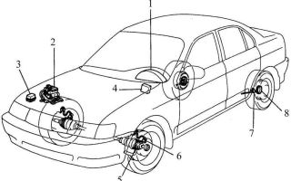
Anti-lock braking system.
The anti-lock brake system (ABS) consists of wheel speed sensors, a brake pedal switch, a hydroelectronic control module and warning lights in the instrument cluster. The anti-lock braking system includes brake force distribution (EBD) and a self-diagnosis system that detects malfunctions of system components.
ABS serves to regulate the pressure in the brake mechanisms of all wheels when braking in difficult road conditions and thereby prevents wheel locking.
The ABS system provides the following benefits:
– avoiding obstacles with a higher degree of safety, including during emergency braking;
– reduction of braking distance during emergency braking while maintaining directional stability and controllability of the vehicle, including when turning.
In the event of a system malfunction, diagnostic functions and maintenance of operation in the event of system failures are provided.
Picture 1
The hydroelectronic control module receives information about vehicle speed, direction of travel and road conditions from the wheel speed sensors and throttle position sensor.
After turning on the ignition, the control unit supplies voltage to the wheel speed sensors. They use the Hall effect and generate an output signal in the form of pulses.
The signal changes in proportion to the rotation frequency of the sensor pulse ring.
Based on this information, the control unit determines the optimal wheel braking mode.
There are the following operating modes of the anti-lock braking system:
– normal braking mode. During normal braking, the intake valve is open and the exhaust valve is closed. When you press the brake pedal, brake fluid is pressurized into the working cylinder and operates the wheel brakes. When the brake pedal is released, brake fluid returns to the master cylinder through the inlet and check valves;
– emergency braking mode. If a wheel locks during emergency braking, the module sends a command to the pump electric motor to reduce the brake fluid supply, then voltage is applied to each solenoid valve.
The intake valve closes and the supply of brake fluid from the master cylinder and pump is shut off; the exhaust valve opens and brake fluid flows from the working cylinder into the main cylinder and then into the reservoir, which causes a decrease in pressure;
– pressure maintenance mode. When the pressure in the working cylinder decreases to a maximum, the module issues a command to maintain brake fluid pressure; voltage is supplied to the intake valve and not to the exhaust valve. In this case, the intake and exhaust valves are closed, and the brake fluid does not leave the working cylinder;
– pressure increase mode. If the module determines that the wheel is not blocked, then voltage is not supplied to the solenoid valves, and the brake fluid enters the working cylinder through the inlet valve, the pressure in which increases.
To diagnose and repair the anti-lock brake system, special equipment and accessories are required, so if it fails, contact a specialized service station.
Source: http://ToyotAuto.net/corolla/osobennosti-konstrukcii-sistemy-abs.html
Toyota Corolla
Pre-check
1. Diagnostic system
a) Release the parking brake lever. b) Check the warning lights. When the ignition is on, check that the ABS warning light and brake warning light are on for 3 seconds.
NOTE: · If the parking brake is applied, or if the brake fluid level is low, the brake warning light will illuminate.
· If the result of checking the indicator is not normal, diagnose the malfunction of the ABS light signaling system) If a hand-held tester is not used:
NOTE: · If the code does not appear, check the diagnostic system or ABS warning light system · For example, the flashing patterns for the normal code and codes 11 and 12 are shown on the left. d) If a hand-held tester is used:
NOTE: Refer to the handheld tester operator's manual for details. e) If a hand-held tester is not used:
ABS system with EBD (TMUK)
1 The car is delivered to the auto repair shop2 Analysis of customer complaints3 Check and clear fault codes and data block4 Confirmation of symptoms of the identified malfunctionSymptom not detected: Go to point 5Symptom detected: Go to point 6 5 Symptom modeling6 Checking the fault code Code is not displayed: Go to point 7Code is displayed: Go to point 8 7 Table of malfunction symptoms Check for fluid leakage and go to point 10 8 Table of fault codes 9 System check
NOTE: When 2 or more DTCs are recorded and the malfunction is not identified, perform system check of other DTCs.10 Malfunction Determination11 Repair12 Confirmation Test
End
NOTE: Steps 3, 6, 9, 12: Diagnostic steps allow the use of a hand-held tester. Anti-emergency function: If a failure occurs in the ABS system, the ABS warning light turns on and the ABS function stops. In addition, if an interruption occurs that disables the EBD, the brake warning lights will illuminate and the EBD will stop operating.
Vehicle terminal system
System Description
When terminals Tc and CG of DLC3 are connected, the ECU displays DTC by flashing the ABS warning light.
Wiring diagram
Verification procedure
1 Check the voltage at terminal DLC3a) Turn on the ignition b) Measure the voltage between terminals Tc and CG DLC3 (terminal Tc).
OK: Voltage: 10-14 V
Go to step 32 Check wiring and connector (DLC3 - ground) a) Check for possible opens and shorts in the harness and connector between the DLC3 CG terminal and ground.
Repair or replace the harness or connector3 Check the wiring and connector (skid control ECU - dlc3) a) Check for possible open and short circuit in the wiring harness and connector between the Tc terminal of the skid control ECU and DLC3.
Repair or replace harness or connector
Check and replace the brake drive unit
Brake Warning Light System
System Description
If the ECU detects a malfunction, the brake warning light comes on and ABS control is stopped at the same time. At the same time, the ECU writes fault codes into memory. Connect terminals Tc and CG of DLC3 to make the brake warning light flash and display fault codes.
Wiring diagram
Verification procedure
1 Reconfirm TROUBLE CODES a) Check fault codes
OK: Normal code
Repair the system indicated by the displayed code2 Check the parking brake switch system a) Check for possible open or short circuit in the parking brake switch system Repair or replace the parking brake switch system3 Check the brake fluid level warning switch system a) Check the brake fluid level in the reservoir b) Check Possible open or short circuit in the brake fluid level warning switch system
OK:
A
Diesel engine
IN
Gas engine
AGo to step 4 BGo to step 6
Repair or replace brake fluid level warning switch system 4 Check vacuum warning switch assembly
Read full entry »
ABS warning light system (does not light up)
System Description
If the ECU detects a malfunction, it stops ABS control, turns on the ABS warning light, and stores a fault code. Connect terminals Tc and CG of DLC3 so that the ABS warning light flashes and output DTC.
Wiring diagram
Verification procedure
NOTE: If using a hand-held tester, start testing from step 1, if not using a hand-held tester, start testing from step 2.
1 Carry out an active test using the hand-held tester (ABS warning light) a) Check that the ABS warning light is displayed on the combined instrument panel using the hand-held tester.
Check and replace the brake drive unit2 Check the indicator unit (ABS warning light) a) Disconnect the skid control ECU connector b) Turn on the ignition c) Check the ABS warning light.
OK: ABS warning light turns on
Repair or replace the indicator unit3 Check the wiring and connector (WA system) a) Check for possible short circuit in the wiring harness between the WA terminal of the skid control ECU and the indicator unit. Repair or replace the harness or connector
Check and replace the brake drive unit
Short circuit in brake light switch system
System Description
DTC No.
DTC Detection Condition
Fault area
S124949
When the voltage at terminal IG1 is 10-16 V, the non-adjustable ABS brake light switch system circuit is open for 1.0 seconds or longer. ● Brake light switch. ● Brake light switch system
Wiring diagram
Verification procedure
1 Check the brake light switch assembly a) Check that the brake light comes on when the brake pedal is pressed and goes off when the brake pedal is released. 2 Check the voltage at the skid control ECU terminal (STP terminal) a) Disconnect the skid control ECU connector . c) Measure the voltage between terminal STP (S1-25) and GND (S1-2, 24) of the skid control ECU wiring harness connector when the brake pedal is depressed.
Voltage: 10-14 V
Check and replace the brake actuator assembly3 Check the wiring and connector (brake light switch - skid control ECU) a) Check for possible open and short circuit in the wiring harness and connector between the brake light and skid control ECU.
Low positive battery voltage or abnormally high positive battery voltage
System Description
This is the power source for the ECU, and therefore the actuators.
DTC No.
DTC Detection Condition
Fault area
S124141
If any of the conditions 1-3 are present: 1. When the vehicle speed is 3 km/h or higher, the IG1 terminal voltage is 10 V for 10 seconds. or more. 2.
When the IG1 terminal voltage is 10V or lower, the solenoid relay circuit is open, the pump motor relay circuit is open, and the solenoid failure detection conditions are set. 3. ECU terminal IG1 voltage remains more than 17 V and continues for 1.
2 sec. or longer. ● Battery ● Charging system ● Power supply system
Wiring diagram
Verification procedure
1 Check the fuse (ECU-IG fuse)a) Remove the ECU-IG fuse from the JB dashboard. b) Check the electrical continuity of the ECU-IG fuse.
OK: There is electrical conductivity
Check for possible short circuit in all wiring harnesses and components related to the ECU-IG2 fuse. Check the battery.
OK: Voltage 10-14 V
Check charging system3 Check skid control ECU connector (voltage at terminal IG1)
If using a handheld tester:
a) Check the condition of the voltage coming from the ECU,
Read full entry »
open circuit in the ABS motor relay system
DTC C027414 B+short circuit in the ABS motor relay system
System Description
The ABS motor relay supplies power to the ABS pump motor. When the ABS is functioning, the ECU turns on the motor relay and the pump motor starts running.
DTC No.
DTC Detection Condition
Fault area
С027313
When the IG1 voltage is 10 V or lower during the initial check or adjustment of the ABS, the pump motor relay turns on, but the relay contact is not turned on for 0.2 seconds or longer. ● ABS motor relay. ● ABS motor relay system
С027414
When the pump motor relay is turned off and the relay contact is turned on for 3 seconds or longer.
Wiring diagram
Verification procedure
NOTE: Start testing at step 1 if using a hand-held tester, and start testing at step 2 if not using a hand-held tester. 1 Perform an active test using a hand-held tester (ABS motor relay)
a) Check the sound of the ABS motor separately when it is running with a hand-held tester.
OK: The sound of the ABS motor should be audible.
Check and replace the brake drive unit 2 Check the skid control ECU connector (+VM voltage at terminal) a) Disconnect the skid control ECU connector. b) Measure the voltage between terminals +BM (S1-23) and GND (S1-2, 24) of the skid control ECU wiring harness connector.
Voltage: 10-14 V
Check and replace drive unit
Read full entry »
Front and rear right wheel speed sensor signal malfunction
Read full entry »
Preheating system (glow plugs)
When the ignition is turned on, the ECM calculates the duration of the glow plug warning light and the duration of the glow plugs. For the calculation, the value of the coolant temperature is used. Since the working part of the spark plugs is made of electrically conductive ceramics, current adjustment on the spark plugs is not necessary.
1
CHECK GLOW PLUG INDICATOR
(a) Turn on the ignition.
(b) Check that the glow plug indicator light comes on.
(c) The control indicator lights up for at least 0.5 seconds.
GO TO 6
2
CHECK ECM
(a) Disconnect ECM connector E16.
(b) Turn the ignition on.
(c) Measure the voltage between terminals GIND and E01 of the ECM connector.
CHECK AND REPLACE ECM
3
CHECK THE FUSE
Read full entry »
- Page 8 of 25
- 1
- …
- 3
- 4
- 5
- 6
- 7
- 8
- 9
- 10
- 11
- 12
- 13
- …
- 25
Source: http://toyota-corolla.ru/tech/page/8/
Repair ABC Toyota Corolla 2007-2010
Since the invention of the ABS (anti-lock braking system), the number of accidents has decreased significantly. Time has passed, and ABC has become an integral attribute of every modern car. Toyota Corolla was no exception.
Like any other electronic system, ABC needs preventative and maintenance, and only proper operation will increase its service life.
In the event of a breakdown, depending on the complexity, ABC Toyota Corolla 2007-2010 repairs can be carried out either by yourself in a garage or by contacting a service center.
Operating a vehicle in harsh climatic and weather environments.
Oxidation in case of depressurization of the control unit itself. Mechanical faults (shock, short circuit). Water or other liquids have entered the unit.
The (ABC) light comes on and does not go out while driving.
The (ABC) light comes on and does not go out when braking. The (ABC) light comes on and does not go out after starting and warming up the engine. The (ABC) light comes on and does not go out after washing the engine. There is a lot of resistance when pressing the brake pedal. When pressing the pedal, the characteristic ABC sound is not heard.
When you start the car, many lights on the instrument panel light up, and after two to three seconds, after testing, they go out. If some indicator does not go out, and this indicator is ABC, then you need to pay attention to this.
There is no particular reason to worry, since the failure of the ABC, especially in the summer, poses virtually no threat. You can easily get where you need to go, and if you have free time, do diagnostics and repairs. I declare with authority, I drove for a long time without ABC, and did not see any special differences.
But, nevertheless, if there is a security system on the car, then it must work, so the ABC Toyota Corolla 2007-2010 repair must be performed.
I forgot to mention one more symptom: ABC activates on dry asphalt at low speed. The remedy may be adding brake fluid to the system, bleeding the block, or replacing the ABC wheel cylinder.
To find out the reason, if you decide to figure it out yourself, you should remove the ABC sensors one by one and measure the resistance.
And if on some sensor it does not correspond to the norm, for some reason it is always on one of the front wheels, then the solution is simple - buy a new one and rearrange it. The procedure is not complicated.
The difficulty is in finding it, but maybe in the Toyota auto parts store in Butovo you will find what you need. Of course, for thrifty people, every thousand counts, and therefore it is easier to fix it yourself.
To do this, you need to dismantle the sensor by unscrewing the fastening nut, use a jigsaw to disconnect the winding from the sensor, then very carefully wind the wire from it. Next, we measure the resistance of the wire with an ohmmeter, select a similar one, and begin winding it onto the winding. It is necessary to count the turns.
If you go overboard, you can remove the excess, but if you make a mistake in the other direction, you will have to redo everything. Now we solder the ends to the sensor and measure the resistance on the assembled unit. The resistance is 99.9% normal. Next, install the ABC sensor in place and secure it with a nut.
Now you are convinced that repair ABC Toyota Corolla 2007-2010 yourself; of course, if the unit is faulty, then you cannot do without service.
Thus, to sum it up, I want to say that almost any malfunction or breakdown of a car is within the capabilities of a person who loves his equipment, is stubborn, in the good sense of the word, and strives to finish what he started.
Sergey Demin specially for the Avtoliteratura website
Source: http://myautobook.ru/publ/toyota_remont/toyota_corolla_2007_2010g/remont_abc_toyota_corolla_2007_2010/8-1-0-33