Installing a car alarm on your own and installation recommendations
Currently, for many people, a car alarm is not only a means of protecting the car from theft and hacking, but also a device used for the comfortable operation of the car.
(opening, closing doors, windows, trunk, turning on/off lights in the cabin, etc.) In this article, I would not like to focus on how a car is stolen, what methods and techniques are used, from bricks to highly intelligent equipment.
I would not like to talk about non-standard solutions when connecting an alarm system, to prevent undesirable situations, at the beginning of writing this article the goal was to combine and unify all knowledge on connecting an alarm system in a car according to a standard scheme, to facilitate the installation and maintenance of security units in your cars, and not bring out a panacea against theft.
1.1 Standard of various alarm manufacturers
Unfortunately, after studying a number of car alarm connection diagrams from different alarm manufacturers (Mongoose, Alligator Sheriff, Tomahawk, Pantera, StarLine, Scher-Khan, etc.
) I came to the conclusion that there is no single unification for alarm systems (security systems) . That is, terminals with the same markings and colors from alarm systems from different manufacturers have different functions during operation.
Apparently this refers to the still ongoing “battles” in the manufacturers’ market for their own standards.
The assumption that this discrepancy is possible due to security is rejected due to the fact that the alarm is installed inside the cabin and in a hard-to-reach place and this is its priority barrier from burglars, and not the use of wires of different colors for the same functions.
In addition, it should be noted that another well-known fact is that burglars never try to figure out what kind of alarm system is installed and how it works. The most important thing is to neutralize it, turn it off and then simply force the car to start, without restoring the standard wiring and functions, but using redundant methods (bypass wires, etc., this is much easier)
Once again, I repeat that the article is intended for ordinary people who want to service the car alarm system on their own (installation and operation), therefore, further, according to the purpose of the article, the basic techniques for mounting and installing alarm components will be given.
The appendix will contain an archive of diagrams for connecting car alarms (this archive will be constantly updated whenever possible, thanks in advance to active readers who will send an electrical diagram for connecting an alarm and a programming table that is not available in the archive for posting on the site).
1.2 Methods for wiring and placing wires in the door-body opening when installing an alarm system
When installing solenoids in the doors and extending wiring to them, the most problematic area from the alarm becomes the place where the wires are constantly bent, namely in the opening where the doors are hung from the body.
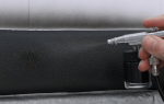
On domestically produced machines, the most suitable option is the use of rubber feed-through tubes, which are fixed at one end in the rack, and the other end freely passes through the hole in the door.
(Figure 1A) In this case, the wires are reliably protected from external influences, the bending radius of the wires passing between the stand and the door is at least 100 mm, which ensures long-term reliable operation of the wire without fractures or breaks.
A section of wire inside the car door is left with a reserve and secured. Currently, you can find different types of bushings on the market. Italian-made bushings are widely used. Unfortunately, they have one significant drawback: they are made of plastic.
The tubes have good oil and petrol resistance, but at temperatures below -30 degrees they become brittle. In our conditions, for installation of alarm wiring, it is better to use domestically produced bushings made of frost-resistant rubber.
The S-loop method is used quite often. (Figure 1B) This method drills misaligned holes in the pillar and in the car door. The wires are passed in such a way that an S-shaped loop is formed. Variations on this theme are quite varied and depend on the level of reputability of the company and the professionalism of the installers.
In the simplest case, bare wires are passed through the holes. It is good if rubber bushings are inserted into the holes, and the wires are enclosed in a PVC tube or wrapped with electrical tape. In more reputable companies, the wires are passed through corrugated rubber tubes, which are sometimes supplied with wires made in Taiwan.
The disadvantages of this method include the fact that the wires work simultaneously to bend and twist. If this method is used on imported cars, where the gap between the pillar and the door is quite large, this is not important, since the bending radius of the wires in this case has acceptable values, and the twisting angle can be completely neglected.
On domestically produced cars, it is better not to use this method, since the gap between the pillar and the door has minimal dimensions, and when the door is closed, the wires bend almost at a right angle. It is not difficult to imagine what will happen to the wires after several hundred doors are closed.
In addition, corrugated rubber tubes made in Taiwan do not stand up to criticism in terms of rubber quality. It is clearly designed for the mild Taiwanese climate and cannot stand the test of our frosts.
Figure 1A Figure 1B
Methods for installing wiring in the body door connector when installing an alarm.
1.3 Connection to the central locking and installation of alarm solenoids in the car doors
When installing solenoids in the door cavity, the most correct solution would be to install them as far as possible, directly from the door opening/closing button rod, since the longest rod will compensate for the angular error of the solenoid relative to the door opening/lock button.
Installing solenoids and connecting them, such problems are getting further and further away from us. Now perhaps the more pressing question is how to connect to the central locking system in a car. So, using the example of connecting an alarm system to the central lock of a Toyota Corolla, model range 2006-2012, let’s consider this case.
First of all, you need to understand the colors of the wires responsible for certain commands. To do this, it is best to use a multimeter. We remove the handle with the central locking control buttons from the driver's door trim. See the article “Removing the Toyota Corolla door handle.” The photo below shows a plug with already calculated central locking control contacts.
The algorithm for finding contacts is simple: switch the multimeter to resistance measurement mode, connect the ground of the device to one of the contacts, press, for example, the close button and look for zero resistance. After this, we release the button if the resistance becomes equal to infinity, this is our option, if not, then we continue the search, going through various combinations. We also find a second contact.
As a result, it turned out that the brown wire is common, yellow and blue are the output control signal. At the same time, it is worth noting that the brown wire is negative, that is, the central locking is controlled by a “negative” control signal.
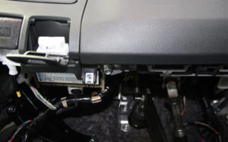
Next, from the driver's door, remove the threshold and the instrument panel cover. The mounting block opens in front of us, it is in it that we will connect to the plus for powering the alarm (the thickest wire is the power wire of the mounting block)
An example of connecting the alarm power supply is shown in the photo below. The alarm power wire is passed through the plug and secured with tape, then the plug is installed in its place.
At the bottom of the threshold, from a bunch of wires coming out of the doors, we find our yellow and blue wire, which we previously identified from the central locking control buttons on the door handle.
We connect to them using clips (in the photo in red) the alarm wires for locking and opening the doors.
Also, to confirm our research, you can look at the electrical circuit for unlocking the doors and lighting the interior of the Toyota Corolla; the yellow wire is for opening; for some reason the blue wire is not shown in the conventional block of the front door I5.
We connect the negative wire of the alarm to the body, in principle, at this point the stage of connecting the alarm to the central locking is completed.
1.4 Installation and operation of limit switches (contacts) during alarm installation
Electrics in a car are increasingly turning into electronics. The use of standard interior lighting switches is becoming increasingly problematic.
If previously the circuit of limit switches for doors was carried out according to the scheme when the power supply of the interior lighting lamp was through a fuse and a limit switch, while the use of these limit switches for signaling ensured a clear alarm when connected to any of the contacts, now the indication unit is usually also involved in this connection scheme . When using this indication unit by connecting to one of the limit switches, the following possible problems arise: - influence on the indication unit through the internal resistance of the alarm; - influence on the alarm through the internal resistance of the indication unit; - impossibility of connecting to only one contact, from one door , and not to all from each door (due to the problems described above); - the use of diodes to prevent the problems described above. As a result, the most optimal solution is the following: - connection to the interior lighting through the interior lamp. The advantage of this connection is the only connection for alarm activation from any of the doors;
– connection at the door contacts, but using diodes.
1.5 Stretching wires in the car and duplicate wires on alarm terminals
It's no secret that when installing an alarm system, it is better to install wiring in closed, dry and protected areas of the body.
It is optimal to use plastic clamps to secure and guide the wiring (Figure 3). Figure 3 (Clamps for fastening wires when installing an alarm system in a car) It is worth noting that duplicate wires are often used in alarm systems.
For example, a contact (limit switch) for opening the doors and trunk. It is most rational to connect duplicate functions through one wire, and cut and isolate the second one with the same function. Subsequently, without possible alternative options, if problems arise with the alarm system, it will be easier to unambiguously determine in which of the circuits the malfunctions are observed.
As a rule, there are not enough standard wires when installing an alarm system, so you have to buy and use additional wires. Recommendations on the required cross-section to ensure operability and safety can be found in the article “Selecting the cross-section of a car wire to connect the load”
1.6 Connecting an external alarm indication in a car
In all the alarm systems I have encountered, the light indication of arming and disarming is carried out through direction indicators.
In this case, two wires are used on the right and left sides with two diodes to prevent the sides from shorting through the alarm.
I consider the most rational for light indication to be the use of dimensions; they have comparable power consumption compared to direction indicators, requiring the connection of only one wire without the use of diodes.
1.7 Connecting the trunk opening function through an additional channel. Using the additional channel (CH2)
Currently, almost all alarm systems on the market support the second channel. Using this channel on the alarm, you can connect to it any electronic device triggered by an impulse (for example, opening the trunk using a solenoid).
From my own example, I can say that this is a very convenient function. There is no need to climb into the cabin every time to open the trunk, especially since the connection is not so difficult (Figure 4).
As a rule, the alarm unit produces a negative pulse (apparently for safety reasons), and the solenoid is triggered by a positive pulse in the standard wiring; in this case, you cannot do without an additional relay.
The pulse current usually ranges from 300-500 mA, so this is also an obstacle to connecting a solenoid without an additional relay.
Figure 4 Connecting the trunk opening function from the alarm.
Examples of mechanical installation of an electric trunk lock for some cars, with subsequent control from an alarm or from a button, can be found in the article “Electric trunk lock.”
1.8 Electrical diagrams for connecting an alarm system in a car
1.8.1 Alarm connection diagrams - manufacturer Alligator (Alligator)
Alligator LX-440 Installation Instructions
Alligator LX-440 User's Instructions
Alligator LX-550 Installation Instructions
Alligator LX-550 User's Instructions
Alligator LX-770 Installation Instructions
User's Instructions
Alligator LX-990 Installation Instructions
Alligator LX-990
User's Instructions Alligator M-300 Installation
Instructions
Alligator M-400 User's Instructions Alligator M-400 Installation Instructions
M-450 User's Instructions
Alligator M-450
Installation
Alligator M Installation Instructions -500 User manual + BONUS – connecting the Alligator D930 alarm system
1.8.2 Alarm connection diagrams - manufacturer Mongoose (Mongoose)
Mongoose Next Installation and operating instructions
Mongoose Two Way Installation and operating instructions
Mongoose DX-1Zone Installation and operating instructions
Mongoose Digital 100 Installation and operating instructions + alarm connection Mongoose IQ160
1.8.3 Alarm connection diagrams - manufacturer Scher_Khan (Sher-Khan), instructions in a self-extracting archive
Scher_Khan 5 Operating instructions
Scher_Khan 5 Installation instructions
Scher_Khan 6 Operating instructions
Scher_Khan 6 Installation instructions
Sher-Khan 7 Operating instructions
Sher-Khan 7 Installation instructions
Sher-Khan 8 Operating instructions
Sher-Khan 8 Installation instructions
Sher- Khan 9 Operating Instructions
Shere Khan 9 Installation Instructions
Shere Khan 10 Operating Instructions
Shere Khan 10 Installation Instructions
Source: http://www.AutoSecret.net/tuning/elektro-tuning/444-alarm
Car alarm connection points for Toyota Corolla
Electrical wiring for Toyota Corolla 2E 1990
| Chain | Color | Polarity | Location |
| 12 V DC | white | positive | ignition switch wiring harness |
| 12 V DC | black red | positive | ignition switch wiring harness |
| starter | black White | positive | ignition switch wiring harness |
| ignition | black/orange | positive | wiring harness from the ignition switch, a break in this wire stops the engine |
| ignition 2 | black/yellow | positive | ignition switch wiring harness |
| ACC | blue red | positive | ignition switch wiring harness |
| direction indicators | green/black green/yellow | positive | wiring harness in steering column or sill |
| door switch wire | Red White | negative | in the door pillar |
| stop signal | green/white | positive | wiring harness in threshold |
| trunk | Red White | negative | trunk light |
Electrical wiring of Toyota Corolla 1998
| Chain | Polarity | Connection |
| +12B | Positive | You need to connect to the 4mm2 white wire coming from the 6-wire white connector on the fuse block. |
| ignition | Positive | b/or - ignition switch |
| ignition 2 | Positive | black/white — ignition switch |
| ACC | Positive | goal/cr — ignition switch |
| starter | Positive | kr - ignition switch |
| Direction indicators | Positive | To control the turn signals, you must connect to the black/green/silver dot wire at position #9 and the green/yellow/silver dot wire at position #3 on the 6-wire white connector located under the fuse box on the bottom of the driver's side pillar. |
| Power windows: Driver's door window | Positive impulse | To close the driver's door window, cut the yellow wire with a cross-section of 1.5 mm2 and make the appropriate connections. |
| Power windows: Passenger door window | Positive impulse | To close the passenger door window, cut the green-red wire with a cross-section of 1.5 mm2 and make the appropriate connections. The connection for the driver's door window is made directly inside the driver's door, and for the passenger's door window in the harness coming out of the driver's door. |
| Engine Lock: Fuel Pump | Positive | To lock out the fuel pump, cut the blue/black/silver dot 1.5mm2 wire at position #3 in the harness coming from the 11-wire white connector located near the bottom of the driver's side pillar and make the appropriate connections. |
| Hood limit switch | negative | Install an additional switch on the decorative grille in which the car's headlights are installed, next to the left headlight. |
| Door and trunk limit switch | negative | Connect to the red/white/silver dot 1mm2 wire at position #11 in the 6-wire white connector harness located at the bottom of the A-pillar on the driver's side. |
| Central locking: | Negative impulse | To lock and unlock the doors, you must connect to the blue-white with a silver dot lock wire in position No. 6 and the blue-red and silver dot unlock wire in position No. 1 in the wiring harness coming from the standard central locking unit mounted directly on the side panel fuse box. |
| Alarm siren placement | Place the siren (monoblock alarm) in the engine compartment on the side panel of the wing on the left side near the air filter. |
Electrical wiring of a Toyota Corolla 1998 - 1999
| ignition | black with yellow in the harness from the lock |
| starter | red or black in the harness from the lock |
| dimensions | green (+) on the driver's side in the white connector under the fuse block |
| turns | green with black, green with yellow |
| low beam | red with white (-) on the steering column |
| tachometer | blue and white in the front connector on the distributor |
| door switch | red with white (-) in the white connector on the driver's side behind the fuse box |
| trunk limit switch | red and white on trunk light |
| central locking | Negative control Locking - blue with black (green with yellow) Unlocking - blue with yellow (blue with red) on the driver's side behind the fuse block in the white connector above the brown connectors |
| brake lights | green and white on a frog |
| window lifters | Reverse remaining on ground Lifting left front window: blue with red; Right front window lift: blue and white; Left rear window lift: Right rear window lift: blue with black; on control buttons |
Electrical wiring of Toyota Corolla 2003
| Chain | Color | Polarity | Location |
| +12 | black red | Positive | at the fuse box |
| ignition | black and white | Positive | at the fuse box |
| starter | red | Positive | at the fuse box |
| turns | green-yellow, green-black | Positive | at the threshold of the waters. |
| doors | red.white,red.yellow | Negative | at the threshold of the waters. |
| c.z. | blue-yellow-open, blue-white-closed | Negative | under the kick panel. |
Electrical wiring of Toyota Corolla 2007
| Chain | Color | Polarity | Location |
| + | white thick medium | Positive | egnition lock |
| starter | white thick extreme | Positive | egnition lock |
| starter 2 | white thin opposite gray | Positive | egnition lock |
| ignition | grey | Positive | egnition lock |
| ignition 2 | white thin opposite white thick | Positive | egnition lock |
| acc | black | Positive | egnition lock |
| c.z. | syn and f next to each other | Negative | from the door water-la white r-m |
| turns | goal and | Positive | water threshold |
| water conc | white | Negative | water threshold |
| end left rear door | Goal | Negative | water threshold |
| end rear door | light green | Negative | water threshold |
| end lane right door | brown | Negative | pass-ra threshold |
| end rear right door | St. green | Negative | pass-ra threshold |
| gasoline pump | light green thick | Positive | water threshold |
| charger | and | Positive | area behind the instrument panel (middle of 3) |
| stop | blue | Positive | frog or water threshold |
| ATTENTION!!! When connecting a remote start, both starters must be connected. |
Electrical wiring of Toyota Corolla 2010
| Chain | Color | Polarity | Location |
| brake | blue | positive | brake pedal, or second from the top from the left in the fuse block |
| pulse | separate wire | diagnostic connector in front of the fuse box | |
| driver's door switch | white | negative | fuse box, top left connector |
| trunk limit switch | light green | negative | fuse box, top left connector |
| rear left door switch | blue | negative | driver threshold |
| turns | blue and yellow | positive | fuse box, top left connector |
| rear right door switch | light green | negative | right threshold |
| front right door switch | brown | negative | right threshold |
| when starting autostart, apply plus to the clutch pedal connector (can be done from the starter) |
ATTENTION! Wire colors and locations may differ from those shown above. This information is advisory in nature and requires mandatory verification !
Source: http://tcorolla-club.ru/texnicheskaya-dokumentaciya/frequently-asked-questions/tochki-podklyucheniya-avtosignalizacii-na-toyota-corolla/
Installation of TOMAHAWK 9010 alarm system on Toyota Allion, Premio, Opa, Corolla in 120 body | Motorist's benefit
We begin the installation of the TOMAHAWK 9010 alarm system by installing the horn and the hood opening sensor. It is recommended to mount the forge in the middle of the top of the engine shield; for this we use one of the bolts securing the throttle cable.
To install the sensor, one of the technological holes under the hood cover above the upper headlight mount is suitable.
After installing the hood sensor, we make a tap with a connection chip so that we can then connect it to the temperature sensor, since they are in the same circuit.
We tighten the wiring harness through the rubber transition in which the standard harness is located. We drag it through with thick wire. There are gray and orange-gray wires under the hood
The next stage of installation will be connecting the wire to the trunk sensor.
The sensor is standard. You need to find the blue wire on the trunk light and solder the wire to it, which we then stretch along the left threshold
Then we connect the trunk opening control relay and the central locking. To do this, we find the multiplex block, it is located on the back of the passenger compartment fuse box (behind the glove compartment), and looks like a small flat box. To get to it, you need to remove the fuse box, disconnect all connectors
After this, the block can be easily removed
This is what the block looks like when disassembled:
Now if you turn it over, you can see the multiplex unit we need, where the remote control for opening the trunk and the central locking relay are located.
To remove the cover you need to unscrew four screws
The multiplex sits tightly in the fuse block connector and in order to pull it out from there you will have to halve the fuse block. Using a screwdriver, pry up the latches and disconnect the block
Here is the board itself
Now you need to solder the wires to the indicated contacts, which are designed to open and close the doors and to the trunk relay
Points 1 and 2 are the opening and closing of the doors, and point 3 is the trunk remote control, all of them are controlled by connecting ground, that is, we connect to the alarm according to a scheme with negative central locking control
Now we make a hole in the multiplex box and bring the wires out
We reassemble in reverse order. Now you need to disassemble the center console to prepare a place for mounting the main alarm unit:
We remove unnecessary wires from the alarm unit - these are the wires that are not used anywhere
- blue (interior lighting), black red (IGN3),
- Yellow-blue (3 additional channel),
- Yellow-red (additional channel 2),
- purple (anti-HI-JACK button)
- Black and white (additional blocking),
- Blue-red (door sensor positive control),
- Yellow-black (1 additional channel),
At the same time, we remove unnecessary wires on the block to the central lock. And solder the blue-gray and green-gray wire from the Central Locking block to the ground wire.
Now you need to remove the instrument panel and solder it to the oil pressure sensor wire - this is a blue wire with a black stripe and connect it to the alarm wire - this is gray-black
Then we connect it to the LED, which turns on when the doors are opened, it is controlled by ground. We disassemble the panel and solder the wire to its cathode
Now this wire needs to be brought out
We connect the same wire to the blue-black one, which is located on the alarm unit
We hook it up to the blue-black wire on the alarm unit.
The panel can be reinstalled.
Now we unsolder the ignition switch block. We find a white-red wire - this is a permanent plus, we solder the red wire from the 6-pin power alarm connector to it.
The black and white wire is the starter, we cut it and hook it up according to the starter blocking relay diagram, not forgetting to solder a diode to it (protection against self-induction, it is on the alarm circuit) and also the black and yellow wire of the whitefish power connector.
The black-yellow thick wire on the lock is the ignition switch, we solder the yellow wire of the power connector to it - this is IGN1.
The black-and-yellow thin wire is ACC, we solder the blue wire of the whitefish power connector to it.
The red-black wire is the climate control switch, I soldered the green IGN2 wire to it
We wind up the resulting harness with electrical tape together with the relay, and connect it to the alarm; we connect the black ground wire to ground on the left threshold below the fuse block.
Now we solder to the turn signal relay, it is located behind the small glove compartment to the right of the steering wheel:
Unfasten the relay to make soldering easier
Then we solder the green-black and green-yellow wires to the relay; oddly enough, they match the colors of the wires on the relay.
Now you need to connect the transceiver to the windshield and install an LED indicator. We install the override button in a secret place
We attach the shock sensor to the metal part of the body using double-sided tape. We carefully twist all the harnesses and wires with zip ties and hide them. We fasten the alarm unit from the bottom of the center console with large ties
Source
.
Related publications:
Source: https://sanekua.ru/ustanovka-signalizacii-tomahawk-9010-na-toyota-allion-premio-opa-corolla-v-120-kuzove/
Blog of a Siberian auto mechanic
Hello, over the weekend they brought me two cars for alarm installation, one of which is a 2003 Toyota Corolla Fielder, a car without a standard immobilizer, which undoubtedly simplifies the task. The Starline A91 alarm system was installed. In this article I will describe the process and lay out the alarm connection points.
So, first we remove the dashboard trim, which is secured with a plastic screw (piston) and a couple of clips.
The device itself is held in place by a screw and two clever latches from below; use a flat-head screwdriver, otherwise there is a high probability of breaking the fasteners.
We take out the instrument panel and remove the plug that comes to it. By the way! As I understand, depending on the modification, the shield can be powered by two plugs, then the door limit switches will be routed along separate wires (each door has its own wire), in our case there is only one plug and all door limit switches (including the trunk limit switch) are hanging on one wire.
Using this plug we can connect, as I already said, to the door switches, tachometer and turn signals.
Next we connect to the central locking. On the Toyota Fielder, as on most Toyota cars, the central locking is controlled by a negative impulse. The wires going to the central locking can be found in the area of the right kick panel, blue chip.
On the blue chip, the green-yellow wire is responsible for closing the doors, and the blue-red wire is responsible for opening them. It’s more convenient, of course, to connect behind a chip.
Next, we connect to the brake pedal frog, to the green-white wire, which is opposite the red one.
Now we can hook up from the power circuit. On the ignition switch: +12 – black and red IGN1 – black and white IGN2 – black and yellow STA – red
ACC – blue-red
We install the hood limit switch, when installed as in the photo, there is no need to trim anything, it works perfectly.
The temperature sensor was screwed to the cylinder head next to the outlet of the pipe to the radiator.
I screwed the siren onto the left glass.
Toyota Fielder alarm connection points (without immo)
| +12 | Black-red | Egnition lock |
| IGN1 | Black and white | Egnition lock |
| IGN2 | Black and yellow | Egnition lock |
| S.T.A. | Red | Egnition lock |
| ACC | Blue-red | Egnition lock |
| Door switches | Blue | Dashboard |
| Tacho signal | White | Dashboard |
| Turns | 2 White | Dashboard |
| Brake | Green-white | Frog brake pedal |
| Central lock | Green-yellow – locking Blue-red – unlocking | Right kick panel |
Source: http://sibmehanik.ru/tochki-podklyucheniya-signalizacii-toyota-fielder-2003-bez-immobilajzera/
Video! – www.fassen.net-Video surfing
Added 1 month. back. Channel: Maroon5VEV…
Maroon 5 – Girls Like You ft. Cardi B
“Girls Like You” is out now. http://smarturl.it/GLY For more, visit: https://www.facebook.com/maroon5 https://twitter.com/maroon5 …
Added 4 months. back. Channel: xxxtentaci…
XXXTENTACION – changes
enjoy. ? HERE: https://xxxtentacion.lnk.to/NEWALBUM.
Added 2 years ago. Channel: Alan Walk…
Alan Walker – Sing Me To Sleep
Listen to “Sing Me To Sleep”: https://AlanWalker.lnk.to/SMTS Merch available at http://bit.ly/AlanWalkerMerch Facebook http://bit.ly/AlanWalker_Facebo…
Added 5 years ago. Channel: Bruno Mars
Bruno Mars – When I Was Your Man [Offici…
Moonshine Jungle Tour 2014 tickets and more info: http://www.brunomars.com/moonshinejungletour Directed by Cameron Duddy & Bruno Mars Bruno Mars …
Added 3 months. back. Channel: wisinoffic…
Wisin – Quisiera Alejarme (Official Video…
Wisin feat Ozuna – Quisiera Alejarme NEW ALBUM “VICTORY” AVAILABLE NOW!: “Victory” is now available! iTunes: http://smarturl.it/VictoryI Apple Music: ...
Added 1 year ago. Channel: Dude Perfe...
Real Life Trick Shots | Dude Perfect
Trick shots should be an everyday thing! Thanks to Kingsford for sponsoring this video! ▻ Click HERE to subscribe to Dude Perfect! http://bit.ly/SubDu…
Added 3 years ago. Channel: Liza Koshy
RECESS WITH LIZZZA / Playground Memories…
Come be an overgrown child with me on the playground! LET'S SHARE SOME COOTIES. I don't wanna grow up. Please give this video a like, babes! Follow my…
Added 7 months. back. Channel: Ed Sheeran
Ed Sheeran – Perfect Symphony (with Andr...
Stream or download this version: https://ad.gt/perfectyt ÷. Out Now: https://atlanti.cr/yt-album Subscribe to Ed's channel: http://bit.ly/SubscribeToE…
Added 4 months. back. Channel: Juice WRLD
Juice WRLD “Lucid Dreams (Forget Me)” (O…
Check out the official audio of “Lucid Dreams (Forget Me)” by Juice WRLD prod by Nick Mira. Listen to the full JuiceWRLD 9 9 9 EP here: http://bit.ly/…
Added 8 years ago. Channel: Bruno Mars
Bruno Mars – Grenade [OFFICIAL VIDEO]
Moonshine Jungle Tour 2014 tickets and more info: http://www.brunomars.com/moonshinejungletour Available now on iTunes! http://smarturl.it/Doo-Wops …..
Added 3 years ago. Channel: Ed Sheeran
Ed Sheeran – Photograph (Official Music …
Download on iTunes: http://smarturl.it/x-itunesdlx Listen on Spotify: http://smarturl.it/stream.photograph Directed by Emil Nava Subscribe to Ed's cha…
Added 2 years ago. Channel: Saturday N…
Star Wars Undercover Boss: Starkiller Ba…
Kylo Ren (Adam Driver) goes undercover as Matt, a radar technician, at Starkiller Base. [Season 41, 2016] #SNL Get more SNL: …
Added 3 weeks. back. Channel: Bebe Rexha
Bebe Rexha – I'm A Mess (Official Lyric …
NEW SINGLE OUT NOW & Debut Album 'Expectations' Out Now: https://beberexha.io/expectations Connect with Bebe: Facebook: http://smarturl.it/fb.
Added 7 days ago. Channel: Dude Perfe...
Ping Pong Trick Shots 4 | Dude Perfect
We take Ping Pong Trick Shots to the CRAZIEST level yet! Special thanks to Nerf for sponsoring this video! ▻Click HERE to get your Nerf Dude Perfect….
Added 4 years ago. Channel: The Tonigh…
Daniel Radcliffe Raps Blackalicious' “Al…
Jimmy challenges hip-hop lover Daniel Radcliffe to rap Blackalicious' tongue-twisting “Alphabet Aerobics.” Subscribe NOW to The Tonight Show Starring…
Added 1 year ago. Channel: Ed Sheeran
Ed Sheeran – Supermarket Flowers [Offici…
Out Now: https://atlanti.cr/yt-album Subscribe to Ed's channel: http://bit.ly/SubscribeToEdSheeran Follow Ed on… Facebook: …
Added 6 years ago. Channel: Bruno Mars
Source: http://www.fassen.net/show/%D0%A3%D1%81%D1%82%D0%B0%D0%BD%D0%BE%D0%B2%D0%BA%D0%B0+ %D1%81%D0%B8%D0%B3%D0%BD%D0%B0%D0%BB%D0%B8%D0%B7%D0%B0%D1%86%D0%B8%D0%B8+Toyota
Installing a car alarm on a Toyota Corolla – Connection points, location and colors of wires
Installing a car alarm on a Toyota Corolla.
You need to connect to the 4mm2 white wire coming from the 6-wire white connector on the fuse block.
To control the turn signals, you must connect to the black/green/silver dot wire at position #9 and the green/yellow/silver dot wire at position #3 on the 6-wire white connector located under the fuse box on the bottom of the driver's side pillar.
Power windows: Driver's door window.
To close the driver's door window, cut the yellow wire with a cross-section of 1.5 mm2 and make the appropriate connections.
Power windows: Passenger door window.
To close the passenger door window, cut the green-red wire with a cross-section of 1.5 mm2 and make the appropriate connections. The connection for the driver's door window is made directly inside the driver's door, and for the passenger's door window in the harness coming out of the driver's door.
Engine blocking: Fuel pump.
To lock out the fuel pump, cut the blue/black/silver dot 1.5mm2 wire at position #3 in the harness coming from the 11-wire white connector located near the bottom of the driver's side pillar and make the appropriate connections.
Hood limit switch.
Install an additional switch on the decorative grille in which the car's headlights are installed, next to the left headlight.
Door and trunk limit switch.
Connect to the red/white/silver dot 1mm2 wire at position #11 in the 6-wire white connector harness located at the bottom of the A-pillar on the driver's side.
To lock and unlock the doors, you must connect to the blue-white with a silver dot lock wire in position No. 6 and the blue-red and silver dot unlock wire in position No. 1 in the wiring harness coming from the standard central locking unit mounted directly on the side panel fuse box.
Alarm siren placement.
Place the siren (monoblock alarm) in the engine compartment on the side panel of the wing on the left side near the air filter.
Upper right fuse box connector.
The lineman fits the Saturn AU-50. You can hide the entire key there, but I only took out the chip from the key, and it was used by the crawler. Shredded the third spare key, which does not have central locking control buttons. The outer shell is rubber and can be cut off with a knife. There is a plastic case inside and you can see the chip there; it is pulled out.
The Toyota interior is well versed. Remove the entire top cover of the torpedo. Everything is held there by clips and three screws. And you need to remove the left and right pillar trims.
And unscrew the airbag, this is done by removing the glove compartment, looking for two 12 bolts at the top, and unscrewing it with the head through the extension. Disconnect the pillow - yellow connector.
When starting up, the system will complain that the airbag is faulty, no problem; when you connect the airbag, this error will disappear on its own.
We hide the signaling and lineman blocks behind the air duct in the middle, spreading them out with a piece of foam rubber.
Source: http://quartz-auto.ru/wordpress/ustanovka-avtosignalizacii-na-toyota-corolla-2.html