Checking the diode bridge with a multimeter
One of the devices that serves to convert alternating current into direct current is diodes. Most often, a bridge circuit is used to implement this process.
Scheme executions
After applying alternating voltage to the input terminals, current begins to flow only through two diodes, while the other two remain closed. Then the closed ones open, passing electric current through them, and the open ones close.
The process is based on the property of a semiconductor device - to pass current through itself in one direction and prevent it from passing back. It will be useful to know how to ring such a circuit if it stops working.
Bridge diode circuits can have two types of designs: either made from individual diodes, or formed as a monolithic structure. The second assembly option is preferable because it takes up less space and is cheaper, however, if at least one element fails, the entire monolithic structure will have to be replaced.
Quick check
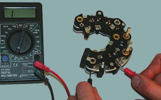
The integrity check procedure is quite simple. If the bridge consists of individual diodes, then you need to unsolder each of the circuit, after which the integrity check is carried out by any tester. Let's take a closer look at how to check a diode bridge with a multimeter.
Having set the “continuity” mode on the multimeter, one of the probes of the device is connected to the first output of the diode, and the other to the second. After ringing in one direction, you need to swap the ends of the multimeter probes and make a second measurement.
If the part is working properly, in one case the device will show the threshold voltage (it fluctuates around 500-700 Ohms), and in the other - unity (the resistance tends to infinity).
Any deviation from these values during testing will indicate that the device is not functioning correctly.
Testing a diode bridge in the form of a monolithic structure has its own specifics. It is necessary to understand which of the terminals and how to connect to each other, as well as what values on the multimeter screen will be normal. We will see the threshold voltage values when:
- The black probe of the multimeter will touch the first terminal of the diode bridge, and the red one will touch the third;
- black - third, red - fourth;
- black – first, red – second;
- black - second, red - fourth.
After this, we connect the ends of the multimeter probes to the terminals of the diode assembly in the reverse order. The multimeter display should show one. If all measurements based on the test results correspond to those specified, then the diode bridge is in good condition.
Diagnostics in the generator
The main element of the car’s electrical system is the generator, because even if the battery is perfectly charged and in full working order, the car will not be able to go far. For this purpose, periodic checks of this device are carried out, the main of which is checking the diode bridge.
First, you need to remove the unit from the generator, after which, setting the multimeter to the continuity mode, begin checking the auxiliary diodes of the generator as follows:
- touch the red probe of the multimeter to the common point on the auxiliary diode bus, and touch the black probe to the diode being tested. The device should show one;
- swap the black and red probes, the threshold voltage values should appear on the screen;
- We ring the remaining additional diodes in the same way.
After this, we proceed to check the power part of the diode bridge of the generator.
We connect the black probe to the bridge plate in which the diode itself is located, and connect the red probe to the terminal of the diode being tested. The device will show one.
Swap the black and red dipsticks. In this state, the threshold voltage value will be displayed on the multimeter screen. We check the remaining elements in the same way.
Alternative way
Checking the diode bridge of the generator can also be done in an alternative way using a homemade tester. To do this, we need a 12-volt light bulb with low power.
To begin with, the bridge housing must be connected to the negative terminal of the battery using a wire, after which we attach any of the lamp contacts to the generator bridge terminal with a negative terminal, and with the second contact we connect terminal “30” to the positive terminal of the battery.
If the lamp starts to glow, this indicates damage to the diode bridge.
We connect the negative terminal of the battery to the bridge body, and connect the positive terminal through the lamp to the mounting bolt of the diode bridge. Flickering or burning indicates a fault in the circuit.
Then we leave the negative terminal there, and touch the “61” point with the positive one. A burning lamp will indicate a malfunction of the additional diodes. As you can see, checking to identify the problem is not at all difficult.
Source: https://EvoSnab.ru/instrument/test/proverka-diodnogo-mosta
How to ring a generator diode bridge with a multimeter
instrument.guru > Useful tips > How to test a generator diode bridge with a multimeter
A diode bridge is an electronic device in an electrical circuit designed to convert alternating current into direct current. It is used in electrical circuits of household appliances and circuits of automobile generators.
It works like this:
- Alternating current, passing through the diode rectifier, is converted into pulsating current. But this is not enough for the normal operation of the rest of the equipment;
- To completely straighten the ripples, a capacitor is installed in the electrical circuit after the bridge. The capacitor acts as a filter and levels out the current diagram. Sometimes, to increase quality, a choke is added to the circuit;
- After processing the electric current, it is important to maintain the voltage in the specified mode. To do this, a voltage stabilizer is connected to the circuit.
Electrical household appliances, as well as car generators, operate according to this scheme.
Malfunctions of rectifiers on cars
A malfunction of the rectifier bridge can be detected if:
- When the engine is running, the battery icon on the instrument panel lights up or flashes; when you turn on the ignition, the indicator should light up. After starting the engine - go out;
- When the ignition is turned on and after the engine starts, the charging indicator with the battery icon does not light up in both cases;
- The brightness of the headlights directly depends on the engine speed. At the same time, car light bulbs burn out more frequently;
- The starter turns, with difficulty starting the engine, or does not turn at all.
If you encounter the problems described above, this means that it’s time to work on the generator. These are indirect indicators of a malfunction of the diode rectifier, but it is not yet a fact that the bridge is at fault. The culprit in this case may be the relay regulator or the generator itself. Therefore, further verification needs to be carried out.
First of all , check to see if the belt is loose . Insufficient belt tension causes slippage. And this prevents the generator from working normally.
After checking the belt, if everything is fine with it, we check the relay regulator. And only after this we begin to check the rectifier bridge. By the way, be sure to check the battery.
The terminals must be clean and the wires securely fastened to them.
How to check a diode bridge with a multimeter
This check can be done without removing the generator from the car. To do this, you will need a multimeter (tester) and free access to the back cover of the generator. If access is difficult, it is better to remove it. In any case, disconnect all external wiring from the generator and remove the voltage regulator.
After that, take a multimeter and set the switch to diode testing mode. If it is not there, then we set the resistance to at least 2 kOhm to measure.
Next, we connect one of the probes to the positive terminal 30 of the generator (a stud on which usually two to four wires go and are secured with a nut), and connect the second one to ground (housing). Then we swap the probes.
In one case, the measuring device should show a certain resistance, in the second - infinity. This way the entire circuit of the rectifier bridge is checked. If the tester shows the same result in both cases, then the rectifier bridge is faulty.
Checking the bridge using a test light
For further and more accurate checking, it is best to use a test light . If it is not available, we assemble a simple circuit.
To do this, you will need two pieces of electrical wire, one meter each, a light bulb (can be removed from the rear light of the car) and a battery. We connect one wire to the negative of the battery.
We cut the second one in half and connect a light bulb into the gap. We connect this wire to the battery positive. Our stand is ready for use.
Now you can continue checking. We connect the negative cable of the battery to the generator housing. The positive one with a light bulb - with one of the diode rectifier mounting bolts. If the light comes on, it means there is a malfunction inside the generator.
Then we connect the plus of the battery to terminal 30 , and connect the minus to the bridge mounting bolt. If the light is on in this case, this indicates the presence of a short circuit.
In any of the above cases, we disassemble the generator, remove the diode bridge and check it separately.
Generator diode bridge ringing
First, remove the plates with rectifier diodes . Some generators need to be disassembled for this, but there are those in which the rectifier bridge is located outside, covered with a plastic cover.
Let's look at checking the diode bridge of the generator of the VAZ 2110 car. Checking the diode assembly can be done with a multimeter or the stand described above using a light bulb and a battery. On the tester we set the mode switch to 2 kOhm.
To check, connect the multimeter probes to the diode terminals. We remember the reading of the measuring device and swap the probes. In one case, the tester readings should be in the range of 570 - 590 Ohms, in the other - infinity.
If the tester readings are the same in both cases - it doesn’t matter what it is, resistance or infinity - then such a diode is faulty. In this case, we replace the entire rectifier bridge.
The prices of voltage rectifiers on the market are relatively inexpensive. You can also change a faulty diode, it will be cheaper, but this requires a certain skill.
The remaining diodes of the bridge are checked in the same way.
How to check the diode bridge of a VAZ 2109, 2107 generator? All of the above-described testing of diode assemblies is suitable for both domestic and foreign generators. The process and principle of checking rectifier bridges is the same everywhere. Sometimes there are some differences, but they do not affect the check order in any way.
Other rectifiers
There are many other rectifier bridges in electronic equipment, the size of which is much smaller than those described above. For example, diode bridge GBU606. Such rectifiers can easily fit into a matchbox, and not just one rectifier unit, but several pieces. It is rectangular in shape.
One corner has a small cut. At the end of the long side there are four thin plates. With these plates it is soldered to the board. And although the characteristics of the GBU606 have significant differences from automobile ones, the principle of operation and purpose remain the same.
This is the conversion of alternating current to direct current.
Why do rectifiers burn out on generators?
There are several reasons here . The main ones:
- Moisture and dirt getting on the plates with the diode assembly;
- Mechanical damage to the inside of the generator;
- Failure to observe polarity when lighting a cigarette;
- Short circuit of electrical wires;
- Excessive load in the vehicle's on-board network.
Keep the generator clean, monitor the insulation of the wiring, and do not disconnect the terminals from the battery while the engine is running. Replace worn generator bearings on time. Carry out preventive maintenance on your vehicle's electrical equipment more often.
If you adhere to these rules, then the possibility of the diode bridge breaking down will sharply decrease.
Source: https://instrument.guru/sovety/kak-prozvonit-diodnyj-most-generatora-multimetrom.html
How to check a diode bridge with a multimeter?
The importance of the diode bridge in the generator is determined by its useful properties of rectifying current.
You can verify the functionality of the diode bridge only on an installed generator; removing and disassembling it can take a lot of time and effort.
However, knowing certain subtleties of the operation of electrical appliances, you can find out whether you are holding a working diode bridge in your hands or not? Today we will tell you how to test a generator diode bridge, but first you will learn what it is for.
The role of the diode bridge in the generator
As is known from electrical engineering sciences, there are two types of electric current - alternating and direct.
Their main difference is that in alternating current charged particles move in different directions, but in direct current only in one direction.
Alternating current has good economics in terms of transmitting it over long distances, but many electrical appliances now operate only on direct current.
In addition, to charge a car battery and operate many electrical appliances, direct current is required, which cannot be obtained from a generator. It is for these purposes that a diode bridge is installed in the generator.
The diode bridge is made in the form of two metal plates that conduct electric current. Special semiconductor elements - diodes - are built throughout the entire area of the plates, which are installed in an alternating order. The essence of the operation of diodes always and everywhere is that they pass a quantity such as current only in one single direction, thus rectifying the voltage.
The alternating voltage coming from the generator ensures a change in the direction of electron movement. Therefore, to obtain a constant voltage, it is necessary not only to block the passage of electrons in the “wrong” direction, but also to redirect them so that both phases of the alternating current work to create a direct current.
This task is performed by the diode bridge. Thanks to alternating current, voltage alternately appears at the terminals of the phases, which makes it possible to separate positive voltage from negative.
In this case, each diode of the bridge passes voltage only in one direction, so two diodes are connected to each terminal of the generator, separating the positive and negative voltage.
There are often generator models that produce not only positive voltage relative to the body, but also negative voltage, so they have three diodes connected to each winding terminal. On many modern machines, the diode bridge is more complex, but the general principle of operation is unchanged, and the battery acts as a capacitor that dampens voltage fluctuations.
Diode bridge test circuit
It often happens that the diode bridge simply fails. This can happen if the polarity of the battery is reversed or an electrical short occurs in the generator. When purchasing a new one, or when repairing an old diode bridge, it must be checked before installing it on the car. To do this, you can use two methods, which are listed below.
Malfunctions
There are only two constant voltage sources in the car that ensure the operation of the on-board network - the battery and the generator. Therefore, any malfunction of the diode bridge necessarily affects the operation of the on-board network.
If your new battery runs out quickly, the headlights are dim, or the starter is difficult to start in cold weather, there is a high probability that the problem is in the diode bridge.
If the receiver or CD/USB player begins to distort the sound while the engine is running, then there is a high probability that the problem is in the diode bridge of the generator.
When one of the bridge diodes is broken or broken, instead of a stable pulsating voltage, a voltage with dips appears at the generator output.
Indeed, during the corresponding half-cycle, the diode cannot transmit voltage to the on-board network, which is why the failure occurs. The battery to some extent compensates for these failures using its resources, but the overall network voltage becomes slightly lower.
In addition, failures are sources of electromagnetic interference, which negatively affect sound-reproducing equipment.
Bridge diagnostics using a multimeter + Video
The only way to properly check the diode bridge is to remove the generator from the engine, disconnect the bridge from it and test it with a tester. After all, the problem may be not only in the diode bridge, but also in the windings, contacts or voltage regulator.
The procedure for removing and disassembling the generator differs on different machines, so use the repair or maintenance manual for your machine. After removing and disassembling the generator, remove the diode bridge from it. On some devices it is connected to the generator using bolts, on others using soldering.
Use paint to mark the generator and diode bridge so as not to confuse its orientation during installation. After removing the diode bridge, take the tester (multimeter) and switch it to resistance measurement mode with sound indication.
A multimeter is a universal device designed to measure electrical quantities and test the performance of other electrical devices and elements. Connect the probes of the device to both terminals of the diode.
On many bridges, the negative terminal of half the diodes is connected to a central aluminum or steel plate, and half of the positive terminals of the diodes are connected to a metal core - a bare tinned wire with a diameter of at least 1 mm.
To check each diode, first touch the central plate or core with one probe and the opposite terminal of the diode with the other, then swap the probes. If the diode is working properly, then the tester will “squeak” only at a certain position of the probes.
If the device beeps in any order of connecting the probes, then the diode is broken. If the tester does not beep in any test order, then the diode is broken.
The device should emit a beep only when checking one side . All other bridge diodes are checked in the same way.
Another option for checking with a multimeter is more accurate and involves the use of another physical quantity - resistance. To do this, the device switch is set to the new position “1kOm”.
The essence of the measurements does not change, except that the device should show from 500 to 800 Ohms in one direction, and infinity in the other. Thus, the diode can be considered fully operational.
Check with a 12 volt light bulb
If you do not have the appropriate device, you can use a lamp instead. To do this, you can use a battery and a 12 volt lamp. Assemble the lamp-battery circuit and in the open circuit, strip the wires with a knife.
These ends will be probes with which you can check. As you guessed correctly, with one polarity of connection to the diode the lamp should light up, but with the other it should not react.
Only in this case is the diode considered serviceable.
There is another way to check with a lamp, but without disassembling the generator. However, its capabilities allow you to test only groups of diodes as a whole. Assemble the same lamp-battery circuit and make free ends at the break in the circuit. Measurements are performed in 4 stages:
- First stage . Absolutely all diodes are checked. One of the free ends is connected to the negative terminal of the generator, and the second to the output contact “30”. If the lamp lights up, you can safely judge that there is a short circuit in the diode circuit (damage to a single or a certain group of diodes at the same time).
- Second phase . Now you need to check the “minus” group of semiconductor elements. To do this, the minus must be connected to the ground of the generator (or housing), and the plus must be tightly leaned against the bolt on which the diode bridge is attached. If the light comes on or starts blinking, it means there is a malfunction in the negative group of the diode bridge.
- Third stage . Next, the positive group of diodes is tested. The negative end of the lamp goes to the diode bridge mounting bolt, and the positive end is installed at terminal “30”. Any lighting of the lamp indicates the presence of a short circuit.
- Fourth stage . The secondary group is checked last. To do this, you need to leave the negative end in the same place, and place the positive end on the “61” pin. If the lamp lights up, this is also a sign of a certain malfunction.
This is how a diode bridge is checked. This is where it ends. As you can see, this is not at all difficult, and you can cope with it without special knowledge in the field of electrical engineering.
Source: http://VipWash.ru/elektrika-avtomobilya/kak-proverit-diodnyy-most-multimetrom
Generator diode bridge, checking faults with a multimeter, removing, replacing or repairing it yourself, connection diagram
A generator diode bridge is present exclusively in “on-board power plants” of alternating current.
Since most passenger cars are equipped with alternating current generators, a rectifier with diodes and a zener diode is present in each of them.
Usually this unit is built into the generator, but there are remote diode bridges for convenient service, repair and replacement of diodes.
Rice. 1 The generator rectifier is a diode bridge with a zener diode
Purpose of the rectifier
Since alternating current generators are more advanced, compact and repairable compared to direct current modifications, a generator diode bridge is added to the design by default to convert alternating current to direct current.
Rice. 2 Connection diagram of the diode block
Rectifier design
In the literal sense, a rectifier is not able to “straighten” alternating voltage. This unit received its name because of the operating principle of the diodes included in it:
- alternating current periodically changes the direction of movement in the circuit;
- diodes pass it in only one direction and cut off currents of reverse polarity;
- so that power surges in the network are invisible to the powered consumer, 3 diodes are installed in one direction, the remaining 3 in the other.
Rice. 3 Operating principle of the generator rectifier
Currently, high-power diodes have a classic design; low-power semiconductor devices of this type are made in the form of a silicon junction on a board. However, to remove high temperatures from the body or silicon junction, both modifications are either embedded in the heat sink plate or equipped with their own individual radiators.
Rice. 4 Power 1 and additional 2 diodes are assembled on a heat-sinking horseshoe
If a silicon junction or a full-fledged diode in the housing breaks down, the diode bridge of the generator or individual semiconductors included in its composition must be replaced.
Main diode bridge
The lower figure shows sinusoids and the direction of current movement in the generator and diode bridge.
Rice. 5 Voltage direction in AC graph and rectifier circuit
The positive value is conditionally taken to be the voltage directed to the 0 point of the stator winding. After the rectifier, the current in the consumer load flows only in the positive direction, that is, from the “+” of the generator to its mass “-”.
Therefore, the power diode bridge (main) uses large-sized 25 - 30 A diodes, the power of which can be further increased due to the additional rectifier arm discussed below.
Unlike other components of the “auto power plant”, a visual inspection does not allow us to identify any faults in the diode bridge of the generator. The rectifier requires only hardware diagnostics with a multimeter.
The diodes are located on a horseshoe-shaped heat sink plate under the back cover of the generator. On remote rectifiers, the diode bridge is located near the generator; instead of plates of the classical configuration, a regular board can be used. In this case, a finned radiator is placed on the body of each diode.
Additional diodes
The main difficulty in the design of a car generator is that the excitation winding of its armature is also a consumer of constant voltage. This coil uses the generator's own diode bridge:
- 3 additional diodes cut off the battery current when the engine is not running;
- negative diodes are taken from the main (power) bridge of the generator.
Rice. 7 Additional diodes
Instead of powerful semiconductor devices, small-sized 2 A diodes are used.
Zener diode
Since the amount of voltage generated by the machine’s generator directly depends on the speed of the crankshaft, which transmits torque to its pulley, “spikes” of up to 20 V are possible in the on-board network, which is harmful for consumers. To eliminate frequent repairs, the easiest way is to connect the rectifier diode bridge via a zener diode:
- this semiconductor device cuts off current of reverse polarity by analogy with a diode, but only up to a certain value called stabilization voltage;
- when the voltage from the stator windings increases to 25 - 30 V, the zener diode begins to pass excess voltage, but in the opposite direction;
- At the “+” terminal of the generator, the correct current value for the on-board network and battery charging is maintained.
When diagnosing a rectifier, checking the diode bridge of the generator with a multimeter is carried out indirectly:
- a normal diode should have “infinite” resistance in one direction, 500 - 700 Ohms in the opposite direction;
- If, when moving the tester probes, the ohmmeter readings do not change, the indicator displays 0 or infinity, the diode is broken and needs to be replaced.
The check is described in more detail in the following paragraphs of this manual.
Additional rectifier arm
Phase voltages are characterized by a deviation of the voltage graph from a sinusoid. Therefore, a generator circuit with an additional rectifier arm is only possible when the stator windings are connected in a star:
- the shape of the phase voltages in this case differs from the sinusoid by the harmonic value;
- this characteristic (third phase harmonic) is present only in phase voltage and is absent in linear voltage;
- The harmonic power can be used as an additional arm by adding diodes at the 0 point of the stator phase windings.
Rice. 9 Circuit with an additional rectifier arm
The magnitude of the shoulder is 5–15% of the generator power, but it occurs only at speeds above 3000 rpm. The durability of the rectifier also depends on the performance of the voltage regulator. But repairs are available to the owner of the car after disassembling the generator.
Rectifier faults
Since the generator rectifier assembly consists of several semiconductor devices and is protected by a cover in 90% of cases, diagnostics will require electrical tools and partial disassembly of the generator. However, in some cases, the driver can hear signs of a diode bridge malfunction:
- when pulsations occur (alternating voltage is supplied to the on-board network instead of direct voltage), the electric motors of some consumers can reproduce sounds by analogy with a speaker;
- Most often, the drive of the power windows and stove “squeaks”, and the tone changes when the speed of these devices changes, and not the crankshaft speed.
In all other cases, malfunctions of the vehicle generator in the rectifier assembly are diagnosed exclusively by instruments. To do this, you will need a diagram for connecting the diode bridge in a specific modification of the generator, since the symptoms of a mechanical failure are completely similar to the breakdown of electrical parts.
Diagnostics of breakdowns
The rectifier assembly is assembled using various technologies - some parts are attached mechanically, small diodes are soldered into the circuit, large ones are usually pressed in. Therefore, repair of the rectifier may be required, not only if the semiconductor elements fail, but also if they are installed incorrectly on the “horseshoe” of the heat sink plate.
The diagnostic technique is as follows:
- the back cover is removed from the generator to provide access to the diodes;
- the plate is supplied with a “–” wire from the battery, it is pressed against the housing on the generator, one wire of the lamp touches the diode at the point where the stator winding is connected, the second – to the “+” of the battery, if there is a breakdown, the light will light up;
- The tester is set to 1 kOhm ohmmeter mode; if you swap the multimeter probes, the readings should change from 0 to 400 - 800 Ohms in different directions.
Rice. 10 Diagnostics of the rectifier with a lampFig. 11 Diagnostics with a multimeter
In most cases, the diode bridge burns when moisture penetrates.
Repair and replacement of diode bridge
Since the rectifier device is simple, and the cost of the entire unit is low, the choice of repairing or replacing diodes depends mainly on the availability of free time from the car owner:
- You will have to remove the rectifier assembly in any case;
- Replacing a generator with your own hands will cost a little more, but it will be faster;
- knocking out and pressing in new diodes takes longer, but is cheaper financially;
- if moisture gets on the rectifier assembly regularly, it is easier to remove the diode bridge and take it to a separate unit under the hood, protecting it with a homemade housing, since a working on-board network is worth the time spent.
The main mistake when replacing the “horseshoe” of the generator rectifier is shorting the two plates with a bolt. This fastener is swapped from the old diode bridge, and the insulator remains in the square mounting hole. It must be removed and moved to a new location before replacing the diode bridge.
Rice. 12 The insulator under the bolt must be moved to the seat
There are dielectric spacers (getinax or textolite) on the three screws securing the stator windings. The fourth screw without a similar washer is attached to a hole specially designed for it, so it is better to remember its location before removing it.
Rice. 13 One screw is installed without a dielectric washer
When purchasing diodes secondhand on the market or after installing a set of semiconductor devices from your own supplies, their malfunction may be detected:
- in a cold state, the diode “rings” normally (resistance 500 - 700 Ohms in one direction, infinity in the opposite direction);
- After starting the internal combustion engine, when the bridge is heated, the diode “breaks through” and does not cut off the negative voltage value.
Therefore, before checking the diode bridge of the generator with a multimeter, it is better to do it in a state heated to 50 - 80 degrees.
Removing the diode bridge of the generator
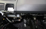
Frequent repairs of the rectifier unit are inevitable during extreme use of an SUV - crossing rivers, “mud baths” of the car while fishing and hunting. Therefore, this category of car owners solves the problem radically by moving the rectifier along with the voltage regulator relay to a separate unit, higher under the hood.
For example, the bottom photo shows a diode bridge of a car generator inside the air filter housing.
Rice. 14 Remote diode bridge in the filter housing
The main nuances of tuning in this case are:
- the filter housing protects the electronics from moisture;
- the cooling problem is completely solved;
- the maintainability of the unit is increased, there is no need to disassemble the generator;
- the terminals are reinforced, a larger cross-section wire is used;
- the heat-shrinkable material was not subjected to high-temperature treatment, so the bundle inside it remained soft;
- A bridge with 8 90 A diodes was used.
If necessary, the remote unit can be mounted inside the cabin, for example, behind the passenger seat.
Source: https://SwapMotor.ru/ustrojstvo-dvigatelya/diodnyj-most-generatora.html
How to check the diode bridge of a VAZ generator at home
Most motorists are comfortable with electronics, especially in modern cars; this is not surprising, given the complexity of modern engines. A large number of different sensors and wiring instills fear in “our brother”... However, there are things that at first glance look very complicated, but in fact their repair and diagnostics are a piece of cake.
Today we will talk about how to check a diode bridge with your own hands , while saving money and time on a trip to specialists at a car service center. I once wrote about how to repair a VAZ 2101 generator, this time we will talk specifically about the diode bridge, or more precisely about how to check it at home.
It’s probably not worth talking about the role of a generator in a car; everyone knows that this is a very important part, without which one cannot imagine an engine. The service life of the battery, which receives charging from the generator, largely depends on the performance of the generator.
A diode bridge consists of four or six diodes that convert alternating current into direct current according to the principle of a bipolar rectification method.
The rectifier diodes of the generator play the role of a gateway that allows current to flow in only one direction, preventing current from the vehicle’s on-board electrical network from passing to the stator windings.
The diodes are located on the generator body and tend to burn out, there are several reasons for this.
Common causes of diode burnout:
- Ingress of moisture (for example, during engine washing).
- Dust, oil and dirt that can get into the generator while driving.
- When “lighting the car” when the battery is completely discharged, in case you accidentally mixed up “+” and “-“.
In fact, there are a large number of situations in which the diode bridge burns out, but of course we will not describe them.
How to check a VAZ diode bridge at home?
In order to check a diode bridge, you do not need to have any super knowledge or tools, it is enough to have an understanding of what a generator and a diode bridge are and to have a tester (multimeter) or a “control” (12 volt light bulb) on hand.
Method number 1 using a light bulb
- Connect the diode bridge plate (housing) to the negative terminal of the battery, while the plate should be pressed tightly against the generator body.
- Then you need to take a light bulb and connect one end to the “positive” terminal of the battery, and connect the other end to the output terminal of additional diodes, and then to the “positive” terminal bolt and to the connection points of the stator winding.
- The light bulb must be in good working order and should not light up when touched; if it does light up, you can safely conclude that the diode bridge is broken.
Method No. 2 checking the diode bridge for open circuit
- Connect the “-” plate of the test lamp to the “+” battery.
- Take the other end of the “control” and connect it to the “-” battery, then check at the same points as described above, only in this case the light should light up; if it doesn’t light up or lights up very weakly, you have a broken diode bridge.
Method No. 3 checking using a tester (multimeter)
This method involves completely removing the entire diode bridge from the generator. Diodes are checked individually.
- Take the tester, set it to the “ringing” mode (when, when two electrodes of the tester are shorted, it rings or beeps; if there is no such option, set it to 1 kOhm mode).
- Connect the electrodes to both ends of the diode, then swap the leads. A diode is considered to be working if it shows 400-700 Ohms in one direction and infinity in the other. If you have infinity in both directions, the diode is broken. If there is resistance, but small or the same on both sides, the diode is broken and requires replacement.
In order to replace a diode, it is enough to have a working diode and a good soldering iron, and skills will not hurt, of course. If you don’t want to bother, change the entire diode bridge assembly, it will be faster, but more expensive.
vaz-remont.ru
Source: http://vaz-remont.ru/kak-proverit-diodnyj-most-generatora-vaz-v-domashnix-usloviyax/
How to check the generator on a VAZ-2114: multimeter and diode bridge
Many motorists have encountered the fact that the voltage in the on-board network of a VAZ-2114 car has dropped. This is due to the fact that malfunctions appeared in the generator. Direct causes may be brushes and diode bridge .
Of course, repairing this unit is usually expensive and the car enthusiast tries to either repair the part on his own or buy a used one.
It is not a fact that the second option will last long, so it is recommended to repair the original one, which will certainly last longer.
The video below will tell you about checking the operation of the generator on the VAZ-2114 (+ its overhaul):
Generator design on the VAZ-2114
Generator 37.
3701
Before you begin directly carrying out repair operations on the generator, you need to know the structure of this spare part.
The generator for VAZ 2113-2115 cars is marked as 37.3701, and is suitable not only for this family, but also for cars of the GAZ family. So, let's look at what parts this unit is made of.
VAZ generator device
Generator 37.
3701: 1 – cover on the side of the slip rings; 2 – rectifier block; 3 – rectifier block valve; 4 – screw for fastening the rectifier unit; 5 – contact ring; 6 – rear ball bearing; 7 – capacitor; 8 – rotor shaft; 9 – output “30” of the generator; 10 – output “61” of the generator; 11 – voltage regulator; 12 – terminal “B” of the voltage regulator; 13 – brush; 14 – stud securing the generator to the tension bar; 15 – pulley with fan; 16 – rotor pole piece; 17 – spacer sleeve; 18 – front ball bearing; 19 – drive side cover; 20 – rotor winding; 21 – stator; 22 – stator winding; 23 – rotor pole piece; 24 – buffer sleeve; 25 – bushing; 26 – clamping sleeve
Dismantling the generator
In order to dismantle the generator, you need to know its location. The diagram below shows not only the fastening device, but also the auxiliary fastening parts.
Layout of the generator and additional components
Removing the generator: 1 – tension bar; 2 – generator; 3 – generator mounting bracket; 4 – generator drive belt; 5 – generator drive pulley
Visual location of the generator on the engine
Also, before removing the generator, it is worth understanding the diagram for connecting the part to the rest of the electrical circuit components:
Electrical diagram for connecting the generatorElectrical diagram for connecting the generator
Connection diagram of the generator system 37.3701: 1 – battery; 2 – generator; 3 – mounting block; 4 – battery charge indicator lamp, located in the instrument cluster; 5 – ignition switch
Now that the basic circuits have been reviewed, you can proceed directly to the step-by-step process of removing the generator from the car. First of all, you will need tools, namely: keys for 8, 10 and 13; flat-head screwdriver. So, let's start the process:
- Disconnect the positive power cable of the generator.
Unscrew the generator power wires
- Loosen the bottom nut on the mounting bracket.
Unscrew the bottom nut securing the generator
- Now, we perform the same operation with the upper mount.
Unscrew the top nut securing the generator
- Loosen the tension bolt and remove the belt.
Unscrew the tension bolt
- Remove the clamping bar.
Removing the clamping bar
- We remove the generator.
Removing the generator from the car
Now that the unit has been dismantled, you can begin checking it.
Generator check
There are two ways to accurately test a generator: on a bench and using an oscilloscope. It is worth considering both methods using visual diagrams.
Stand
A special testing stand is equipped with a volt-ohmmeter and an ammeter, which display performance indicators in an artificially created on-board network. There is also an additional motor that, using a belt, drives the generator itself. So, it’s worth seeing what this stand looks like:
Checking the generator using a stand
Connection diagram for testing the generator on the stand: 1 – test lamp 12 V, 3 W; 2 – generator; 3 – voltmeter; 4 – rheostat; 5 – ammeter; 6 – switch; 7 – battery
Now the installed generator can be turned on by first setting the output voltage on the rheostat to 13V. In this case, the rotor speed should reach 5000 rpm. The stand should operate for 10-12 minutes, and then it is necessary to measure the current strength that is given out. If it is less than 55A, then the generator is faulty and requires repair.
Oscilloscope
An oscilloscope will immediately show a generator malfunction, so diagnostics using it is considered more accurate. Let's consider the verification principle:
Connection diagram of the generator to the oscilloscope for testing
Connection diagram for checking the generator with an oscilloscope: 1 – switch; 2 – generator; 3 – voltmeter; 4 – rheostat; 5 – ammeter; 6 – switch; 7 – battery
Disassembly process
The protective cover latches are marked with arrows
Let's consider what parts the generator as a whole consists of. This is necessary in order to understand how the process itself goes.
Generator disassembly diagram
Generator parts 37.
3701: 1 – capacitor; 2 – voltage regulator assembled with brush holder; 3 – terminal block for additional diodes; 4 – insulating bushings; 5 – rectifier block; 6 – contact bolt; 7 – stator; 8 – rotor; 9 – spacer sleeve; 10 – inner bearing mounting washer; 11 – drive side cover; 12 – pulley; 13 – outer bearing mounting washer; 14 – coupling bolt; 15 – front rotor ball bearing; 16 – bushing; 17 – cover from the side of the slip rings; 18 – buffer sleeve; 19 – clamping sleeve.
Components of the VAZ-2114 generator
Signs of a diode bridge malfunction: diagnostics
Diode bridge on the generator
Generator problems directly depend on the health of the diode bridge. You can check the serviceability of this unit in three ways:
- By connecting a test lamp with a current of 12V to it.
- Visual inspection of the rectifier for broken contact wires.
- Diagnostic operations using a multimeter.
There can be two reasons for the failure of this unit:
- Passed the full resource of use.
- Ingress of foreign elements into the generator (water, dirt, etc.), which caused a short circuit and failure of the element.
Let's take a closer look at the process of diode bridge diagnostics.
Diagnostics using a warning lamp
Diode bridge diagnostic diagram using a test lamp
For diagnostics you will need a battery and a warning light. So, you need to connect the rectifier plate to the minus terminal. Next, we connect the test lamp with the “plus” wire to the battery, and the “minus” wire to additional diodes. We connect the “plus terminal” to the bolt, which is located near the stator winding of the rectifier. If the lamp lights up, then the unit is faulty.
Rectifier inspection
Rectifier testing process
To perform this diagnosis, you will also need a battery. We connect the test lamp with the minus wire to the plus terminal of the battery. Then, “plus” the lamp to the “minus” battery. We connect the “plus terminal” to the bolt, which is located near the stator winding of the rectifier. If the lamp lights up, then the unit is faulty.
Diagnostics using a multimeter
Checking the diode bridge using a tester
Remove the rectifier from the housing. Set the multimeter to “ringing” mode. Now, one by one, you need to short-circuit the electrodes of the device to the diodes. If it makes a “squeaking” sound, then the rectifier is working; if not, then the part is “dead” and requires replacement.
Signs of brush failure
The arrow indicates worn brushes. Their length is 3 mm instead of the required 5 mm. Relay regulator from a different angle
If you look at the brushes, their surface will be worn out, and the power supply control wires will be broken. This is the main sign of a malfunction, which may indicate that their natural depreciation has come. There are several signs that they are out of order:
- Voltage drop in the on-board network at idle speed.
- At dusk or at night, external lighting (headlights) dims.
- No battery charging.
Generator selection
If it is not possible to repair the old generator, it will need to be replaced. We have already written about which one to choose in the material: “Choosing which generator is best to install on the VAZ-2114.”
conclusions
To check the generator on a VAZ-2114 car, namely the brushes and diode bridge, it is necessary to dismantle and disassemble the unit. This process is quite lengthy and requires some knowledge.
Not all even experienced motorists are able to perform this operation on their own.
Therefore, if a car owner is not sure that he is able to repair the generator on his own, it is recommended to contact a car service center.
Source: http://carfrance.ru/kak-proverit-generator-vaz-2114-diodnyj-most-i-shhetki/