Fuse box for Toyota Corolla 120 body: where is it located
Toyota Corolla, like any other car, has fuse blocks. But not all vehicle owners know where they are located. This article will tell you how to find and detect these elements, as well as the explanation of each of the fuses located in a separate block.
What are fuses used for?
Fuses of different types.
Fuses are necessary to prevent fires and short circuits in the vehicle's wiring. So, when a short circuit occurs, the first to fail is the fuse element, which burns out. It breaks the network of a certain element of the car, which ensures safety from fire wiring.
Good and bad fuse.
Location of fuse blocks and decoding for Toyota Corolla 120 body
Location of fuse boxes.
In the Toyota Corolla vehicle in the E120 body there are five mounting blocks, which are located both in the engine compartment and in the vehicle interior. Finding these blocks is quite easy if you know where to look.
Another diagram of the location of fuse blocks
Fuse block No. 1
The first fuse box is located on the left side of the engine compartment. The lid is held on by latches that are fairly easy to remove. In addition to fuses, this block contains control relays.
First fuse box, general view. First fuse box. And another view of the fuse box. Where is the fuse box located and how does it open.
Let's look at the decoding of the fuses and relays of the first block of the Toyota Corolla E120:
| Fuse | Current strength | Purpose |
| A | 50A | electric power steering |
| b | 40A | headlights |
| With | 50A | engine management (2ZZ-GE) |
| d | 100A | charging system, rear window defroster |
| e | 30A | headlight washer |
| f | 30A | radiator and condenser fans |
| g | 30A | or VSC No. 1 (40A) ABS |
| h | 40A | or VSC No. 2 (40A) ABS |
| 1 | 15A | right headlight |
| 2 | 15A | left headlight |
| 3 | 10A | sound signal |
| 4 | 10A | direction indicators and hazard warning lights |
| 5 | 5A | charging system |
| 6 | — | spare |
| 7 | 15A | engine control, automatic transmission operating mode indicators |
| 8 | 15A | clock, instrument cluster, headlights, interior lighting, automatic air conditioning, radio, warning system, headlights not turned off, remote control, central locking, ABS (VSC) |
| 9 | 30A | AM2 ignition switch circuit |
| 10 | — | backup circuit |
| 11 | — | backup circuit |
| 12 | — | backup circuit |
| 13 | — | backup circuit |
| Relay | |
| Location | Purpose |
| A | Electric power steering relay |
| IN | Air conditioning compressor clutch e/m relay |
| WITH | Horn relay |
| D | Injection relay |
| E | Radiator fan relay #2 |
| F | Radiator fan relay #1 |
Location of mounting blocks in the engine compartment.
Fuse block No. 2
The second fuse box is located in the passenger compartment, on the left under the steering wheel. To get to the element, you need to pull on yourself. It looks like a kind of glove compartment.
Location of the second and fifth fuse blocks in the car interior. Location of the second fuse block. Technical diagram of the second fuse block.
Let's look at the decoding of the fuses and relays of the second unit of the Toyota Corolla E120:
| Fuse | Current strength | Purpose |
| 1 | — | not used |
| 2 | — | not used |
| 3 | — | not used |
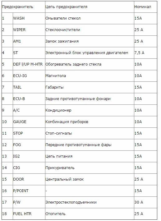
| 4 | 25A | Fuel heater |
| 5 | 15A | Cigarette lighter, audio system, clock, power mirror controls |
| 6 | 15A | Sensors and meters, SRS air spring system, multiport fuel injection system/sequential multiport fuel injection system, starter system, charging system |
| 7 | 10A | Exterior mirror defogger, multi-port fuel injection system/sequential multi-port fuel injection system |
| 8 | 7.5A | Multiport fuel injection system/sequential multiport fuel injection system, sensors and counters |
| 9 | 10A | Air conditioning system, anti-lock brake system, vehicle stability control system, rear fog lamp |
| 10 | 25A | Fuse "CIG" |
| 11 | 15A | Taillights, License Plate Lights, Parking Lights, Headlight Beam Control, Instrument Panel Illumination, Clock, Headlight Cleaner, Front Fog Lights, Seat Heaters, Multiport Fuel Injection/Sequential Multiport Injection System |
| 12 | 20A | Electric window |
| 13 | 15A | Brake lights, high mounted brake light, lock control system, multiport fuel injection system/sequential multiport fuel injection system, anti-lock brake system, vehicle stability control system |
| 14 | 15A | Front fog lights |
| 15 | 25A | Power door locking system |
| 16 | — | not used |
| 17 | 10A | Air conditioning system |
| 18 | 7.5A | On-board diagnostic system |
| 19 | 10A | Gauges and Meters, Air Conditioning System, Power Windows, Reversing Signals, Daytime Running Lights, Rear Window Defogger, Automatic Transmission Overdrive System, Power Door Locking System, Charging System, Hazard Flashers, Automatic Anti-Glare Interior Mirror, System SRS airbags, reminiscent of the front passenger's seat belt warning light |
| 20 | 15A | Seat heaters |
| 21 | 15A | Windshield wipers and windshield washer |
| 22 | 10A | SRS air spring system, electric cooling fan, anti-lock brakes, gear lock control system, power steering system, headlight cleaner |
| 23 | 25A | Windshield wipers and washer, rear window wipers and washer |
| 24 | 40A | Rear window defogger, fuse “M-HTR/DEF I-UP” |
| 25 | 30A | Power window, power sunroof |
| 26 | 40A | Air conditioning system, fuse "A/C" |
| Relay | |
| Location | Purpose |
| A | Ignition relay |
| B | Rear window defroster relay |
| C | Fuel pump relay |
| D | Power window relay |
| E | Starter relay |
| F | Electric windows, electric sunroof |
| G | Rear window defroster, air conditioning, heater |
Fuse block No. 3
The third control unit is located in the engine compartment of the Toyota Corolla E120, near the hood lock. This block is not present on all vehicles, and this indicator depends on the vehicle configuration. It all depends on the presence of air conditioning in the vehicle, since the relays are responsible specifically for the air conditioning fan.
Technical diagram of the third mounting block.
Let's look at the decoding of the relay of the third block of the Toyota Corolla E120:
| Relay | |
| Location | Purpose |
| 1 | Radiator fan relay #1 |
| 2 | Radiator fan relay #3 |
| 3 | Radiator fan relay #2 |
Fuse block No. 4
As in the case of the third block, the fourth is not installed on the vehicle model. This is the VSC unit, which is responsible for the operation of the ABS system.
Scheme of the fourth mounting block.
Let's look at the decoding of the fuses and relays of the fourth block of the Toyota Corolla E120:
| Fuse | Current strength | Purpose |
| 1 | 7.5A | ABS (VSC) |
| Relay | |
| Location | Purpose |
| A | ABS electric pump relay |
| B | ABS valve relay |
Fuse block No. 5
The fifth relay block is located in the car interior, under the instrument panel on the right. To get to the block, you need to remove the right air duct by prying it off with a screwdriver.
The fuse box is located under the air duct. Technical diagram of mounting block No. 5. Location of the fifth mounting block.
Let's look at the decoding of the relay of the fifth block of the Toyota Corolla E120:
| Relay | |
| Location | Purpose |
| A | Idle speed control system relay |
| B | Fog light relay |
| C | Relay for accessories |
| D | Heater relay |
conclusions
As can be seen from the materials, the Toyota Corolla E120 has five fuse blocks, which are located in the engine compartment and interior of the vehicle. The change of elements occurs typically and is typical for all types of cars.
Source: http://carfrance.ru/raspolozhenie-blokov-predoxranitelej-toyota-corolla-e120-rasshifrovka-predoxranitelej/
Fuses for Toyota Corolla: their blocks, where they are located
All electrical circuits of the car are protected by fuses, they are also called protective devices or protective inserts, as well as circuit breakers, which are installed in two blocks. These units are installed in different places of the Toyota Corolla car.
If any insert burns out, it must be replaced. You can do it yourself if you know where the fuse assembly is located, its number, and also the installation location of the failed one.
The central unit is located under the vehicle's instrument panel. It is located on the wall. It is covered with an easily removable decorative panel. The second block is located in the engine compartment. For Toyota models that have air conditioning installed, its location is slightly different; it is located next to the battery.
What indicates a failed fuse?
Toyota Corolla cars provide protection for electrical equipment against short circuit currents. If a fault occurs in the electrical circuit, especially during a short circuit, the current of the protected circuit increases many times over. The fuse blows, thereby protecting the wires from fire.
All protection devices have their own designations on the panel where they are installed. They are needed so that it is possible to quickly detect them and then replace them. Fuses are equipped with knife-shaped contacts, are easily removed from their sockets, and are easily replaced. Replacing them does not require special equipment, but is done manually.
This is easy to do, since the fuse housing is made of transparent plastic and if you look closely, you can visually see a burnt-out thread. You can also use an ohmmeter or tester to check. There are times when the body of the device may begin to melt.
About the types of fuse links
Fuse links installed on Toyota Corolla cars come in three types. Conventionally, they are designated type A, type B, type C.
They all have a different design, so the malfunction of each of them has its own peculiarity. So, for a device of type A, a fault in the form of a burnt-out thread can only be seen when the device itself is removed.
The burnt thread can be seen on the side, between the contacts, thereby determining whether it needs to be changed or not.
Fuse links of type B are arranged somewhat differently. The condition of the conductive thread can be seen, and also the integrity can be checked without removing it from the socket. This can be seen if you look at the insert from above. The same can be said about devices of type C; they differ only in the types of fuse links.
Instructions for replacing fuses
If, when diagnosing the electrical equipment of a Toyota Corolla, a burnt-out protective insert is detected, it must be replaced. Before replacement, it is necessary to turn off all electrical consumers and only then proceed with replacement.
Specialists use various tweezers in their work for these purposes. With their help, it is easy to remove and then insert any device being tested. In new Toyota cars, tweezers are located under the cover of the unit, which is installed under the hood.
The blocks are made in such a way that it is not always possible to perform this operation with your fingers.
If a newly installed device fails immediately after replacement, it is necessary to check all the electrical circuits it protects. It is possible that there is a short circuit in the circuit. The rated current of the fuse link is indicated by markings on its body. Inserts of the same power have their own color and it is quite difficult to confuse them when replacing them.
Toyota Corolla E120-E130 cars have 5 units in the electrical circuits with protective devices and relays. Two blocks are located in the car's interior, and three in the engine compartment.
In the cabin there are blocks numbered 2 and 5. To access block No. 2, remove the cover of the mini-box; it is located on the panel near the driver’s left foot.
No. 5 is located behind the air duct grille on the dashboard on the right side of the Toyota Corolla.
In the Toyota engine compartment, three blocks are located as follows. No. 1 is located on the left side in the direction of travel closer to the windshield, No. 4 is installed on the right side near the front suspension strut.
No. 3 is located near the radiator of the engine cooling system. All of them are closed with plastic covers, on the back of which there is a numbering of fuses and a designation of the protected circuits.
In the 2008 Toyota Corolla models, electrical equipment protection is located in only two units. They are arranged as follows. One is in the car interior near the driver’s feet, at the bottom of the door, and the second is located in the engine compartment, not far from the air filter.
The unit in the engine compartment serves all high current consumers and current relays. A unit with protective inserts, which is located in the cabin, serves all electrical devices with a small current load. These units have a similar design and consist of several parts. This is a relay part, a block with protective inserts and sockets with spare inserts.
Modern Toyota Corolla cars have a complex electrical circuit. Therefore, seriously weigh your options before you begin troubleshooting.
Source: http://CorollaCar.ru/remont/elektrooborudovanie/predoxraniteli-tojota-korolla.html
Replacing fuses in TOYOTA COROLLA FIELDER. Designation of Toyota Fielder fuses

Every user has a TOYOTA COROLLA FIELDER. Not a repairman or an auto electrician should have a basic set of knowledge in his head about the electrical equipment of his car.
Most citizens use complex Japanese equipment at the household level without climbing inside and not knowing how everything is arranged on the TV (DVD, video camera), BUT where to connect the cord leading to the outlet, which buttons to press and that everything should be turned on ideally via the network filter, most people guess.
Often, windshield wipers stopping, power windows not working, or headlights not working are not a disaster, but only a blown corresponding fuse that needs to be replaced.
In order to change the fuse, you need to buy a new one, and it is advisable to go to the store with a burned out old one if you are not sure what to take, because... The cost of a mistake can be high.
TOYOTA COROLLA FIELDER has two fuse and relay blocks:
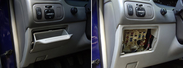
The mounting block under the instrument panel FIELDER is located behind the glove compartment lid. above. If you have changed the cabin filter at least once. then everything is clear to you. If it’s not clear, go ahead - open the glove compartment lid, carefully squeeze the outside of the side of the lid on both sides with your hands and pull it towards you - the glove compartment lid has completely come out of the grooves. The fuse box is on top behind the cover.
The mounting block in the FIELDER engine compartment is located under the hood, on the right, next to the inner wing console, as shown in the figure - position 3 . To rice. To see it in full size, click on it.
The principle of operation of fuses is
when an overload occurs in the electrical circuits of COROLLA FIELDER
– be melted before electrical wiring and electrical equipment are damaged.
To remove and install type “A” fuses, use a special tweezers-type puller.
Procedure for replacing fuses:
– before replacing, turn off the ignition and all electrical appliances.
– Install fuses only of the required current rating.
– it is prohibited to use other objects instead of fuses (“bugs”).
– if after replacement the fuse blows again, then it is necessary to check the electrical circuits for open circuits and short circuits.
On the cover of the TOYOTA fuse box, the names of the TOYOTA COROLLA FIELDER electrical circuits and the characteristics of the fuses themselves are indicated - 10 A; 20 A. or others
If there is no spare fuse. then, as a last resort, the TOYOTA manufacturer recommends removing the fuse from the “CIG” (cigarette lighter) position and using it if the current ratings are the same (15 A).
If a fuse with a rated amperage is not available, use a fuse with a lower amperage value, as close to the rated amperage as possible. A set of spare fuses should be available from TOYOTA.
Fuse box
How to disassemble the instrument panel on a Toyota Corolla e12
Source: http://toyota2blog.ru/page/zamena-predohranitelej-v-toyota-corolla-fielder
Toyota Corolla electrical equipment - fuses
The vehicle uses DC electrical equipment with a rated voltage of 12 V. The electrical equipment of the vehicle is made according to a single-wire circuit: the negative terminals of sources and consumers of electricity are connected to ground, which serves as the second wire. In turn, the role of “mass” is played by the car body.
Consumers are powered from the battery (with the engine not running) and the generator (with the engine running). A special feature of the electrical circuit of the Toyota Corolla is the use of a multiplex CAN bus (Controller Area Network) for data transmission.
Via the CAN bus, electronic control units (ECUs) for the engine, instrument cluster, ABS, air conditioning system, passive safety system (SRS), as well as the instrument panel mounting block, steering angle sensor, yaw rate sensor and lateral acceleration.
The multiplex CAN bus is a twisted pair of wires. The system provides high data transfer speed (500 kbit/s) and can significantly reduce the number of wires in the car.
The CAN bus is connected to the diagnostic connector located under the instrument panel on the left side. If a malfunction occurs in the CAN bus, the ECUs connected to it at that moment write a fault code into memory. This code and other fault codes stored in the memory of the electronic units can be read by connecting a scanning device to the diagnostic connector.
Toyota Corolla diagrams
Carry out any work on the vehicle's electrical equipment only with the battery disconnected.
The battery can only be disconnected or connected with the ignition off. When checking electrical equipment circuits, it is prohibited to short the wires to ground (check the serviceability of the circuits for a spark), as this can lead to failure of electrical equipment elements.
It is prohibited to use fuses that are not provided for by the design of the vehicle or are designed for a higher current, and also to use wire instead of fuses. When replacing fuses, do not use screwdrivers or metal tools - this may cause a short circuit in the electrical circuits.
It is forbidden to disconnect the battery while the engine is running; violation of this rule will cause failure of the voltage regulator and elements of the vehicle's electronic equipment.
To avoid failure of the diodes of the generator rectifier unit, it is prohibited to check them with a megger or a test lamp powered by a voltage of more than 12 V, and to check the electrical circuits on the car with such devices without disconnecting the wires from the generator.
It is necessary to check the insulation resistance of the generator stator winding with increased voltage on the generator removed from the vehicle, with the stator winding terminals disconnected from the rectifier unit.
When carrying out electric welding work on a car, it is necessary to disconnect the wires from the terminals of the battery and generator, as well as the connectors with wires from the electronic engine control unit. Do not touch the ignition system components and high-voltage wires while the engine is running. Do not lay low voltage wires in the same bundle with high voltage wires. Regularly clean the battery terminals and wire tips from oxides and dirt. When recharging the battery using a charger, disconnect the wires from the battery terminals.
Numbers of relays and fuse links in the mounting block located in the cabin
A typical electrical circuit may include the main electrical element, various switches, relays, electric motors, fuses, fuses or circuit breakers related to this element, wiring and connectors that connect the main element to the battery and body ground. Before you begin troubleshooting any electrical circuit, carefully study the corresponding diagram in order to understand its functionality as clearly as possible. The scope of troubleshooting is usually narrowed by gradually identifying and eliminating normally functioning elements of the same circuit. If several elements or circuits fail at the same time, the most likely cause of failure is the blown of the corresponding fuse or a loss of contact with ground (different circuits in many cases can be shorted to one fuse or ground terminal). Failures of electrical equipment are often explained by simple reasons, such as corrosion of connector contacts, failure of a fuse, burnt-out fuse link or damaged relay. Visually check the condition of all fuses, wiring and connectors on the circuit before proceeding with a more detailed check of the serviceability of its components. If diagnostic tools are used for troubleshooting, carefully plan (in accordance with the supplied electrical diagrams) at which points in the circuit and in what sequence the device should be connected to most effectively identify the fault. The main diagnostic instruments include an electrical circuit tester or voltmeter (a 12-volt test lamp with a set of connecting wires can also be used), an open circuit indicator (probe), which includes the lamp's own power source and a set of connecting wires. In addition, you should always have in your car a set of wires for starting the engine from an external source (the battery of another car), equipped with alligator clips and preferably an electrical circuit breaker. They can be used to bypass and connect various elements of electrical equipment when diagnosing a circuit. As already mentioned, before you start checking the circuit using diagnostic equipment, determine the location of its connection using the diagrams. Checks for the presence of supply voltage are carried out in the event of an electrical circuit failure. Connect one of the leads of the electrical circuit tester to the negative terminal of the battery or ensure good contact with the vehicle body. Connect the other tester lead to the terminal on the circuit being tested, preferably the one closest to the battery or fuse. If the tester's warning lamp lights up, there is supply voltage on this section of the circuit, which confirms the serviceability of the circuit between this point in the circuit and the battery. Proceed in the same way, explore the rest of the chain. Detection of a supply voltage violation indicates the presence of a fault between this point in the circuit and the last one previously tested (where the supply voltage was). In most cases, the cause of failure is loosening of the contact connectors and damage to the contacts themselves (oxidation). Finding the location of the short circuit. One method of finding a short circuit is to remove the fuse and connect a test lamp or voltmeter instead. There should be no voltage in the circuit. Twitch the wiring while watching the test lamp. If the light begins to blink, there is a short to ground somewhere in this wiring harness, possibly caused by chafing of the wire insulation. A similar test can be carried out for each of the components of the electrical circuit by turning on the corresponding switches. Checking the reliability of contact with ground. Disconnect the battery and connect one of the wires of the probe lamp, which has an independent power source, to a point with known good contact with ground. Connect the other lamp wire to the wiring harness or connector pin being tested. If the lamp lights up, contact with ground is OK (and vice versa). The continuity check is carried out before detecting an open circuit. After turning off power to the circuit, test it using a self-powered test lamp. Connect the probe leads to both ends of the circuit. If the control lamp lights up, there is no open circuit. If the lamp does not light up, this indicates an open circuit. In a similar way, you can check the serviceability of the switch by connecting a probe to its contacts. When the switch is turned to the “ON” position, the probe lamp should light up. Localization of the break point. When diagnosing a section of an electrical circuit that is suspected of having a break, it is quite difficult to visually detect the cause of the malfunction, since it can be difficult to visually check the terminals for corrosion or poor quality of their contacts due to limited access to them (usually the terminals are covered by the contact connector housing). A sharp twitching of the housing of the wiring harness block on the sensor or the wiring harness itself in many cases leads to restoration of contact. Keep this in mind when trying to isolate the cause of a circuit failure that is suspected of being open. Unstable failures may be the result of terminal oxidation or poor contact quality. Diagnosing faults in electrical circuits is not a difficult task, provided it is clear that electric current flows to all consumers (lamp, electric motor, etc.) from the battery through wires through switches, relays, fuses, fuse links, and then returns into the battery through the “ground” (body) of the car. Any problems associated with electrical equipment failure can be caused by the loss of electrical current from the battery or the return of current to the battery.
Numbers of relays and fuse links in the mounting block located in the cabin
Fuse numbers in the mounting block located in the passenger compartment
Designation of fuses, fuses and relays in the mounting block located in the engine compartment
Most power supply circuits for vehicle electrical equipment are protected by fuses.
Powerful current consumers are connected via relays. Fuses and relays are installed in mounting blocks, which are located in the vehicle interior and in the engine compartment. Most of the fuses are installed in the interior relay and fuse mounting block, located on the left side of the instrument panel at the bottom (the electronic control unit for the body electrical equipment is installed in the same block). The purpose of fuses and relays (their numbers are shown in the figures) is indicated in the table. In addition, fuses, relays and fuse links are located in the 8th mounting block installed in the engine compartment on the left side in the direction of travel. The table indicates the purpose of these fuses, fuses and relays, but on a specific car model, some of the circuits listed in the table may be missing. 1. To gain access to the fuses of the mounting block located in the passenger compartment, press the latch... 2. ...and remove the cover of the mounting block. On the front side of the cover there is a diagram of the location of the fuses.
3. Before replacing a blown fuse, find out the cause of its blown and eliminate it. When troubleshooting, look at the circuits indicated in the table that this fuse protects. Do not replace fuses with jumpers or fuses designed for a different amperage, or with homemade jumpers - this may damage electrical appliances and even cause a fire. 4 Remove the fuse to be replaced using tweezers. 5. This is what a blown fuse looks like (the jumper inside the holder shown by the arrow has burned out and opened).
To replace the fuse, use a spare fuse of the same rating (and color). 6. To access the fuses and relays of the mounting block located in the engine compartment, press the latch. 7. remove the cover. A diagram of the location of the relays and fuses is printed on the inside of the cover.
8. If necessary, remove the relay or fuse link by rocking it slightly from side to side. 9. Use special tweezers to replace fuses. 10. Install the parts in the reverse order of removal.
Source: http://toyoinfo.ru/news/1/2012-11-30-983
Location and description of fuses and relays E110 - Photo report
The main locations of the fuse and relay blocks are indicated by numbers in the figure from the manual:
Fuses and relays located in the passenger compartment.
The main fuse box in the cabin (in Fig. No. 6) is located below the steering wheel, closer to the door (for models with left-hand drive).
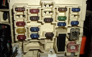
We open the panel, which is a pencil case for small items and pieces of paper. Remove it by pulling it up and towards you. Below it is the fuse box:
1 - TURN (7.
5A) - direction indicators and hazard warning lights 2 - reserve 3 - GAUGE (10A) - lighting, dimensions, air conditioning system, reversing lights, sunroof control system, power windows, rear window defroster 4 - WIP (20A) - (wiper) wiper and windshield washer and rear door glass 5 — I-UP/M-HTR (10A) — idle speed increase system/side mirror heating 6 — ECU-IG (10A) — fuel injection system 7 — IGN (7.5A) — battery charging system, fuel injection system, airbag system (SRS) 8 - STOP (15A) - brake lights, additional brake light 9 - TAIL (15A) - tail lights, instruments and sensors, clock, cigarette lighter, audio system, rear window heater, license plate light, fuel injection systems, air conditioning system, alarm system, central locking 10,11 - reserve 12 - OBD (7.5A) - OBD-2 diagnostic system 13 - ECU-B (7.5A) - airbag system safety, rear fog lights 14 — ST (5A) — starting system 15 — D/L (30A) — central locking 16 — FOG (15A) — fog lights 17 — S-HTR (15A) — (Seat Heater) heated seats 18 — reserve 19 — CIG (15A) — audio system, clock, cigarette lighter, electric side mirrors 20 — DEF (40A) (gray) — rear window heater, fuse: DEF I-UP/M-HTR
21 — Power (30A) (pink) — electric windows, electric sunroof
The same block from the reverse side:
A - rear window defroster relay B - headroom relay
C - integrated relay
The fuse box next to the passenger's foot (left-hand drive) (in Fig. No. 7).
1 — A/C (15A) — air conditioning system, fan 2 — HTR M (40A) — heater fan
A - heater relay
The relay block is to the left of the driver’s foot (in Fig. No. 4).
A - heater relay B - fuel pump switch relay
C - main power relay
Fuses and relays in the engine compartment.
The fuse box is next to the left pillar (in Fig. No. 2).
1 - reserve 2,3,4 - SPARE (5A, 7.
5A, 15A) - spare fuses 5 - MAIN (40A) - starting system, headlights fuses: HEAD(RH) or HEAD(RH-UPR), HEAD(LH) or HEAD(LH-UPR) 6 - DOME (15A) - audio system, interior lighting, local lighting, trunk lighting, clock 7 - HAZARD (10A) - direction indicators and hazard warning lights 8 - AM2 (15A) - second ignition circuit, air conditioning system, fusible links ST and IGN 9 - reserve 10 - HEAD(LH) or HEAD(LH-UPR) (10A) - left headlight 11 - ALT-S (5A) - charging system (generator) 12 - HEAD(RH) or HEAD(RH-UPR) (10A) - right headlight 13 - EFI or F-HTR (15A) - electronic engine control unit 14 - HORN (10A) - sound signal 15 - FAN (30A) - fans
16 - AM1 (50A) - first ignition switch circuit, fuses: CIG, TURN, GAUGE, ECU-IG, WIP, S-HTR
FL ALT (100A) - main fuse, fuses: FAN, CDS, HTR, A/C
FL ABS (50A) - ABS fuse, fuses: AM1, POWER, D/L, TAIL, FOG, ECU-B, STOP, DEF , DEF I-UP/M-HTR
A - ST - starter relay B - HEAD - headlight relay C - EFI or F-HTR - injection system relay D - ENGINE MAIN - engine relay E - FAN No 1 - cooling fan relay
F - HORN - horn relay
The fuse box is next to the battery (in Fig. No. 3).
1 - CDS (30A) - air conditioning condenser fan A - AC MG - air conditioning compressor magnetic clutch relay B - AC FAN No.3 - radiator fan relay No. 3
C - AC FAN No.2 - radiator fan relay No. 2
The ABS fuse box is located next to the right headlight (in Fig. No. 1).
A - (green) - ABS solenoid valve relay
B - (black) - ABS pump motor relay
Diagnostic connector DLC1. It is located in the engine compartment, next to the master brake cylinder (DLC1 in Fig.).
PS If I made a mistake or missed something, please correct me.
Source: https://corolla.ws/forum/showthread.php?t=16598
Toyota fielder 2009 where are the fuses located?
Every TOYOTA COROLLA FIELDER user, not a repairman or an auto electrician, should have a basic set of knowledge in his head about the electrical equipment of his car.
Most citizens use complex Japanese equipment at the household level without climbing inside and not knowing how everything is arranged on the TV (DVD, video camera), BUT where to connect the cord leading to the outlet, which buttons to press and that everything should be turned on ideally via the network filter, most people guess.
To put it simply, all FIELDER electrical equipment is connected to relay and fuse blocks, the location of which would be useful for even a blonde driving to know.
Often, windshield wipers stopping, power windows not working, or headlights not working are not a disaster, but only a blown corresponding fuse that needs to be replaced.
In order to change the fuse, you need to buy a new one, and it is advisable to go to the store with a burned out old one if you are not sure what to take, because... The cost of a mistake can be high.
TOYOTA COROLLA FIELDER has two fuse and relay blocks:
The mounting block under the FIELDER instrument panel is located behind the glove compartment lid, on top. If you have changed the cabin filter at least once, then everything is clear to you. If it’s not clear, proceed: open the glove compartment lid, carefully squeeze the outside of the side of the lid on both sides with your hands and pull it towards you - the glove compartment lid is completely out of the grooves. The fuse box is on top behind the cover.
The mounting block in the FIELDER engine compartment is located under the hood, on the right, next to the inner wing console, as shown in the figure - position 3 . To rice. To see it in full size, click on it.
when an overload occurs in the electrical circuits of COROLLA FIELDER
- be melted before
Electrical wiring and electrical equipment will be damaged.
To remove and install type “A” fuses, use a special tweezers-type puller.
Procedure for replacing fuses:
- before replacing, turn off the ignition
and all electrical appliances.
only the required current rating.
- it is prohibited to use other
- if after replacement the fuse blows again, then you need to check
electrical circuits for open circuits and short circuits.
On the cover of the TOYOTA fuse box, the names of the TOYOTA COROLLA FIELDER electrical circuits and the characteristics of the fuses themselves are indicated - 10 A; 20 A. or others
If there is no spare fuse, then as a last resort, the TOYOTA manufacturer recommends removing the fuse from the “CIG” (cigarette lighter) position and using it if the current ratings are the same (15 A).
If a fuse with a rated amperage is not available, use a fuse with a lower amperage value, as close to the rated amperage as possible.
Fuse block diagram for Toyota Corolla E120-E130
1. Block No. 1 of fuses and relays in the engine compartment
This block is located under the hood in the upper right corner. In the photo it is indicated as - Block No. 1
Several photos of this block from different cars, to compare the location of fuses and relays.
Block and wiring diagram for the table below
electric power steering
engine management (2ZZ-GE)
charging system, rear window defroster
radiator and condenser fans
or VSC No. 1 (40A) ABS
or VSC No. 2 (40A) ABS
direction indicators and hazard warning lights
engine control, automatic transmission operating mode indicators
clock, instrument cluster, headlights, interior lighting, automatic air conditioning, radio, warning system, headlights not turned off, remote control, central locking, ABS (VSC)
AM2 ignition switch circuit
Electric power steering relay
Air conditioning compressor clutch e/m relay
Horn relay
Injection relay
Radiator fan relay #2
Radiator fan relay #1
2. Block No. 2 of fuses and relays in the cabin
In the cabin, on the lower left side of the driver, there is a cover behind which is located - Block No. 2.
Cigarette lighter, audio system, clock, power mirror controls
Sensors and meters, SRS air spring system, multiport fuel injection system/sequential multiport fuel injection system, starter system, charging system
Exterior mirror defogger, multi-port fuel injection system/sequential multi-port fuel injection system
Multiport fuel injection system/sequential multiport fuel injection system, sensors and counters
Air conditioning system, anti-lock brake system, vehicle stability control system, rear fog lamp
Taillights, License Plate Lights, Parking Lights, Headlight Beam Control, Instrument Panel Illumination, Clock, Headlight Cleaner, Front Fog Lights, Seat Heaters, Multiport Fuel Injection/Sequential Multiport Injection System
Brake lights, high mounted brake light, lock control system, multiport fuel injection system/sequential multiport fuel injection system, anti-lock brake system, vehicle stability control system
Front fog lights
Power door locking system
Air conditioning system
On-board diagnostic system
Gauges and Meters, Air Conditioning System, Power Windows, Reversing Signals, Daytime Running Lights, Rear Window Defogger, Automatic Transmission Overdrive System, Power Door Locking System, Charging System, Hazard Flashers, Automatic Anti-Glare Interior Mirror, System SRS airbags, reminiscent of the front passenger's seat belt warning light
Windshield wipers and windshield washer
SRS air spring system, electric cooling fan, anti-lock brakes, gear lock control system, power steering system, headlight cleaner
Windshield wipers and washer, rear window wipers and washer
Rear window defogger, fuse “M-HTR/DEF I-UP”
Power window, power sunroof
Air conditioning system, fuse "A/C"
Fuse box Toyota Corolla
All electrical circuits of the car are protected by fuses, they are also called protective devices or protective inserts, as well as circuit breakers, which are installed in two blocks.
These units are installed in different places of the Toyota Corolla car. If any insert burns out, it must be replaced.
You can do it yourself if you know where the fuse assembly is located, its number, and also the installation location of the failed one.
The central unit is located under the vehicle's instrument panel. It is located on the wall. It is covered with an easily removable decorative panel. The second block is located in the engine compartment. For Toyota models that have air conditioning installed, its location is slightly different; it is located next to the battery.
What indicates a failed fuse?
Toyota Corolla cars provide protection for electrical equipment against short circuit currents. If a fault occurs in the electrical circuit, especially during a short circuit, the current of the protected circuit increases many times over. The fuse blows, thereby protecting the wires from fire.
All protection devices have their own designations on the panel where they are installed. They are needed so that it is possible to quickly detect them and then replace them. Fuses are equipped with knife-shaped contacts, are easily removed from their sockets, and are easily replaced. Replacing them does not require special equipment, but is done manually.
If any element of an electrical circuit or an entire electronic device fails, the first step is to check the protection of this unit.
This is easy to do, since the fuse housing is made of transparent plastic and if you look closely, you can visually see a burnt-out thread. You can also use an ohmmeter or tester to check. There are times when the body of the device may begin to melt.
About the types of fuse links
Fuse links installed on Toyota Corolla cars come in three types. Conventionally, they are designated type A, type B, type C.
They all have a different design, so the malfunction of each of them has its own peculiarity. So, for a device of type A, a fault in the form of a burnt-out thread can only be seen when the device itself is removed.
The burnt thread can be seen on the side, between the contacts, thereby determining whether it needs to be changed or not.
Fuse links of type B are arranged somewhat differently. The condition of the conductive thread can be seen, and also the integrity can be checked without removing it from the socket. This can be seen if you look at the insert from above. The same can be said about devices of type C; they differ only in the types of fuse links.
Instructions for replacing fuses
If, when diagnosing the electrical equipment of a Toyota Corolla, a burnt-out protective insert is detected, it must be replaced. Before replacement, it is necessary to turn off all electrical consumers and only then proceed with replacement.
Specialists use various tweezers in their work for these purposes. With their help, it is easy to remove and then insert any device being tested. In new Toyota cars, tweezers are located under the cover of the unit, which is installed under the hood.
The blocks are made in such a way that it is not always possible to perform this operation with your fingers.
It is necessary to install a new fuse only as specified in the Toyota Corolla operating instructions. If installed with a lower rated current, it will burn out again when the equipment is turned on, and if with a higher rated current, the electronic unit may fail or the wiring may catch fire.
If a newly installed device fails immediately after replacement, it is necessary to check all the electrical circuits it protects. It is possible that there is a short circuit in the circuit. The rated current of the fuse link is indicated by markings on its body. Inserts of the same power have their own color and it is quite difficult to confuse them when replacing them.
Toyota Corolla E120-E130 cars have 5 units in the electrical circuits with protective devices and relays. Two blocks are located in the car's interior, and three in the engine compartment.
In the cabin there are blocks numbered 2 and 5. To access block No. 2, remove the cover of the mini-box; it is located on the panel near the driver’s left foot.
No. 5 is located behind the air duct grille on the dashboard on the right side of the Toyota Corolla.
In the Toyota engine compartment, three blocks are located as follows. No. 1 is located on the left side in the direction of travel closer to the windshield, No. 4 is installed on the right side near the front suspension strut.
No. 3 is located near the radiator of the engine cooling system. All of them are closed with plastic covers, on the back of which there is a numbering of fuses and a designation of the protected circuits.
In the 2008 Toyota Corolla models, electrical equipment protection is located in only two units. They are arranged as follows. One is in the car interior near the driver’s feet, at the bottom of the door, and the second is located in the engine compartment, not far from the air filter.
The unit in the engine compartment serves all high current consumers and current relays. A unit with protective inserts, which is located in the cabin, serves all electrical devices with a small current load. These units have a similar design and consist of several parts. This is a relay part, a block with protective inserts and sockets with spare inserts.
Modern Toyota Corolla cars have a complex electrical circuit. Therefore, seriously weigh your options before you begin troubleshooting.
Fuses for Toyota Fielder: general information
Every modern car has a huge amount of electronics that need some protection from voltage surges and short circuits.
The most common means of protection is a fuse. As a rule, every car lover has at least once encountered the replacement of these small protectors.
In this article we will talk about fuses on the Fielder - we will find out where they are located and what each of them is responsible for.
Types and location of fuses on Toyota Fielder
For our convenience, the manufacturer has distributed the fuses into separate blocks, which in turn are located in different parts of the car. These blocks can be divided into two main types:
Let's start with the main thing - with the inner box, which is located inside the car and hidden under the dashboard on the driver's side. In order to get to it, you need to open the pencil case for small items and pieces of paper and carefully pull it up and towards you (see photo below).
By removing the pencil case, we gain access to the main, so-called cabin fuses. In the photo below you can see the entire block in more detail.
In any manual for the car (you can download manuals on our website) you can find a detailed diagram and description of the purpose of each of the fuses in this block. For general information, fuses responsible for:
- direction indicators,
- emergency alarm,
- lighting,
- air conditioning system,
- windscreen wipers,
- fuel injection system,
- heating systems,
- starting the power unit,
- audio system,
- cigarette lighter,
- heated seats.
So for those who especially often ask the question: “why doesn’t my clock, cigarette lighter, power windows, etc. work?” — first of all, you should contact this panel in order to check their functionality.
Next, let's move on to the next panel, which is also located in the Fielder's cabin. This panel is located on the dashboard on the right side, that is, on the side of the front passenger seat. Looking lower, in the area of the legs you can see the location of the relay - as we see in the photo and diagram, there are not very many meanings there.
Let's figure out which element is here and what it is responsible for. Meaning one – air conditioning system, fan. Value two – heater fan. And finally, the value “A” is the heater relay. This concludes the consideration of fuses located inside the car, and we move on to examining external fuses, which, as a rule, are located under the hood of the car.
In the photo below we can see the safety device box located under the hood of the car - it is located next to the left front pillar of the car.
On the lid of the box or under it there is a special diagram that will help, using the manual, to decipher and give you the opportunity to understand where certain safety devices are located.
Here you cannot find devices responsible for maintaining the cigarette lighter and similar internal entrails, but you can find fuses: those responsible for the car’s generator, sound signals, ignition circuits, turn signal fuses, and others.
There is no need to describe everything in detail, only for the reason that depending on the year of manufacture of the Fielder, the location of the fuses and their meaning in a particular block may change.
The next block is also located under the hood of the car. You can find it near the car battery - in itself it is small and, as a rule, is of an auxiliary nature. In the photo you can see it in more detail.
Let's look at its main meanings:
1. – air conditioner condenser fan;
A. – relay for the electromagnetic clutch of the main air conditioning compressor;
B. and C. – radiator fan relay.
The next block will be located with the right headlight of the vehicle. As a rule, it contains the fuses responsible for the ABS. In the photo you can see its appearance in more detail.
This concludes our inspection of boxes with safety devices. In the end, I would like to say that before looking for certain safety devices, you should first of all refer to the manual that is suitable for your year of manufacture and your car model - it is not recommended to perform any actions without it.
Since only with it you will know the exact values of a particular fuse, as well as have information on its physical characteristics.
To help ourselves, we pay great attention to the stickers located on the covers or under the covers of the blocks - they will help you decipher the meanings, as well as understand where each fuse is located.
ActionTeaser.ru – teaser advertising
Source: http://thunde.pp.ua/toyota-fielder-2009-gde-nahodyatsya-predohraniteli/