Nuances of dashboard design and diagnostic connector pinout for Toyota cars
Toyota tidy with symbols
To begin with, we suggest that you familiarize yourself with the information regarding the location and designation of elements and icons on the shield.
For example, the instrument panel of a Toyota Corolla in the 120 body is considered:
- Fuel filter element status indicator, used only in diesel car dashboards.
- Vehicle speed limit system activation indicator.
- The orange Check Engine icon, indicating the need for vehicle diagnostics, should always appear when the ignition is turned on, but after starting the engine goes out. If this indicator appears when the engine is running, this indicates that the power unit needs diagnostics. If this indicator blinks, this indicates that there is no stable neoplasm in the ignition system. In this case, the engine speed should be reduced until the indicator stops lighting.
- Front fog light activation lamp.
- Electronic tachometer. This device is designed to demonstrate crankshaft rotation speed. Revolutions are indicated in thousands.
- Left information screen. It displays information regarding the fuel level in the tank, the temperature of the antifreeze when the internal combustion engine is running, as well as the position of the transmission lever.
- The left turn signal activation indicator, designed in the form of a green arrow, always turns on automatically when the steering column stalk is turned. If the light begins to blink twice as often as usual, this indicates that a bulb in one of the cornering headlights has burned out. If the icon lights up continuously or does not blink at all, then most likely there is a problem in the electrical circuit.
- The high beam activation icon is made in the form of a blue headlight.
- The outside light activation indicator always lights up when the headlights are turned on.
- The right turn signal is designed in the form of a green arrow.
- The speedometer is one of the main instruments that the driver pays attention to most often. This device determines the speed of the vehicle.
- Right information screen. When the driver turns on the ignition, it displays data on the outside air temperature, date and time. It also displays information about the trip, including fuel consumption and mileage traveled, data on the average speed of the car, and various warning messages. This display also shows the time since the engine started.
- A light that appears when the rear fog lights are activated.
- An icon that is activated in the event of a malfunction in the ABS system. It should always appear when the ignition is turned on, but after starting the engine it should disappear. If the light is on when the power unit is running, this indicates a malfunction in the system.
- Symbol of the operating status of the system for adjusting the angle of illumination of the optics. Such an indicator is only available in dashboards whose cars are equipped with xenon.
- Symbol of the performance of the traction control system. As with other components, it should appear only when the ignition is turned on.
- The passive safety system performance icon on the instrument panel is designed in the form of a red light bulb. If the indicator starts to light up when the engine is running, then it is necessary to diagnose the Airbag system.
- Indicator of the performance of the engine pre-heating device; this icon is only found on the dashboards of diesel-powered cars.
- LED symbol for the seat belt monitoring system. It always appears when the ignition is activated, but if the driver or passenger is driving without a seat belt fastened, it will also light up while driving. Also, when the indicator is on, a corresponding sound signal will be heard.
- Speed limit activation symbol.
- Control device for dashboard lighting, as well as a key for switching displays on the right screen.
- The gear engaged symbol is used only in cars with a manual or robotic transmission.
- This indicator is a device that monitors the status of the main car systems, the performance of which is displayed on the right screen. Appears only when there are malfunctions in the operation of these systems.
- A key used to switch viewing modes on the right screen.
- The handbrake activation symbol always lights up when the handbrake is on. If there is a problem with the brake system, this indicator will also light up - for example, if there is a lack of brake fluid.
- An icon that appears when problems are detected in the robotic transmission.
- Diode indicator indicating problems with the operation of the electric drive.
- Battery discharge symbol. If it lights up when the engine is running, then you need to check the battery charge and recharge it if necessary (video author - Alexey Valerievich).
Possible faults
Briefly about device malfunctions:
- Indicator burnout. The simplest solution to the problem is the malfunction. A burnt-out indicator must be replaced with a working one.
- The device displays incorrect data. For example, about fuel consumption, engine temperature, etc. In this case, most likely the reason lies in the sensors - for example, coolant temperature, etc. If the sensors are working, then there is a possibility that the data is being sent incorrectly by the control unit.
- No backlight. This problem is usually caused by a malfunction of the power cord responsible for the backlight.
Diagnostic system used in Toyota vehicles
Now let's talk about the diagnostic connectors for Toyota Camry, Corolla, Pajero and other models.
The diagnostic connector is a plug to which an adapter is connected, which is used to read fault codes.
If the diagnostics showed the presence of error codes, this indicates the presence of breakdowns in the operation of certain components. A complete decoding of the codes will allow you to accurately find out about the faults present in the car.
Photo gallery “Types of diagnostic connectors”
1. More complex connectors that were used on some cars manufactured after 19902. Connectors that were also installed on some Toyotas produced after 1990.3. 16-pin connectors that are installed on most cars manufactured after 1998.
Location
Of course, the location of the diagnostic connector may vary depending on the design features of the vehicle.
For example, diagnostic outputs may be located:
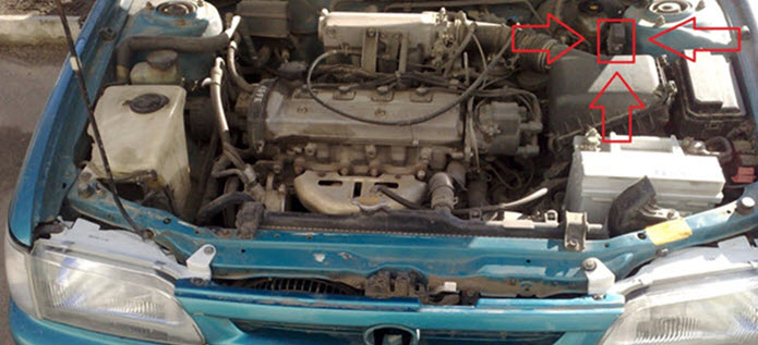
- In the engine compartment. As a rule, in this case, the connector is hidden by a cover on which there is a corresponding inscription.
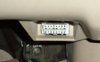
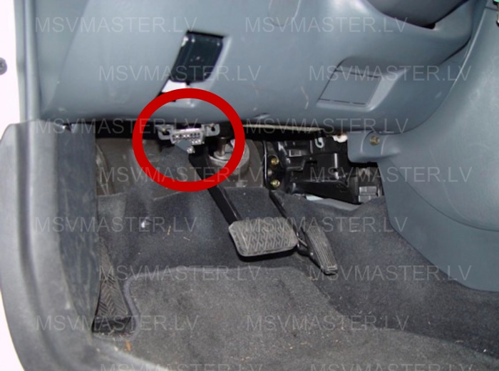
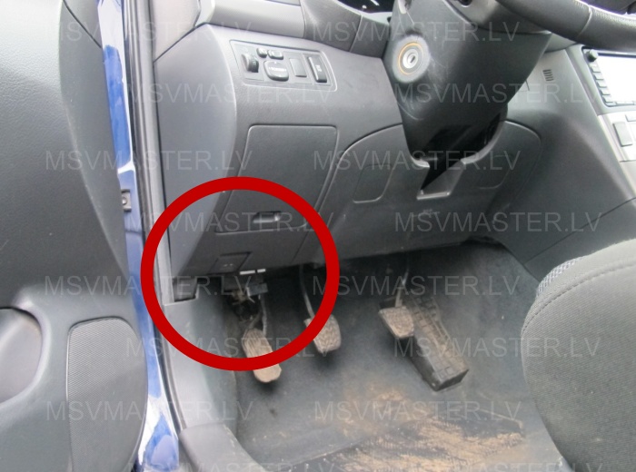
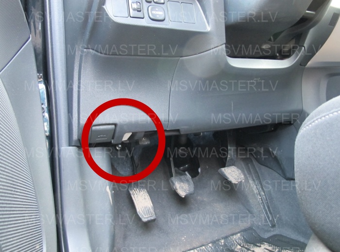
- In the vehicle interior, opposite the driver’s seat, under the center console.
Loading …
Video “Do-it-yourself Toyota diagnostics using a computer”
A detailed video on diagnosing a Toyota Rav4 car through the diagnostic connector using a laptop and software is presented below (author - MrIcemenWhite channel).
Source: http://AvtoZam.com/toyota/raspinovka-diagnosticheskogo-razema/
Toyota Corolla Forum
Engine operation (and everything on it), problems, repairs and spare parts
VITALY Messages: 45 Registered: Jan 19, 2013, 5:31 pm Car: 2008 4ZZ-FE Location: Karelia
#2
Post by VITALY » 05 Feb 2013, 14:40
I connected the following device: Autocom CDP pro
No errors found.
You do not have the necessary permissions to view the attachments in this message.
voldemar Messages: 172 Registered: Jan 11, 2013, 00:59 Location: Kharkov Thanked: 1 time
#3
Post by voldemar » 05 Feb 2013, 22:31
did he even see anything?
I thought that it only takes a scanner that reads K+CAN
VITALY Messages: 45 Registered: Jan 19, 2013, 5:31 pm Car: 2008 4ZZ-FE Location: Karelia
#4
Post by VITALY » 06 Feb 2013, 11:21
Generic OBD Supporting EOBD/OBDII MT/AT 1ZZ-FE 4ZZ-FEABS ABS/VSC Vehicle stability control Immobiliser Airbag BODY Central ECUClimate control AC BODY Main body Cruise Control DiagnoseDriver door Diagnose
Power steering EMPS
validuserHonored Korollov Messages: 6048 Registered: 15 Jan 2013, 14:17 Car: Mazda CX-5 Location: Saratov Thanked: 72 times Thanked: 131 times
#5
Post by validuser » 07 Feb 2013, 09:04
Does it just show errors or allow you to erase them? For example, does it allow you to turn off the pillows?
How about changing the values in the ABS block?
VITALY Messages: 45 Registered: Jan 19, 2013, 5:31 pm Car: 2008 4ZZ-FE Location: Karelia
#6
Post by VITALY » 07 Feb 2013, 14:41
mistakes can definitely be erased.
into my hands for “five seconds.” I got it, a friend was passing through and showed off his purchase (bought it in Sweden)
I managed to scan it. A friend says the scanner has many capabilities, changing parameters is possible.
– Automatic polling of all systems and electronic control units (ECUs) of the connected vehicle using Autocom ISS (Intelligent System Scan) technology – Reading and deleting fault codes (DTC) – Adaptation of components and assemblies of adaptations – Display of unit operating parameters in real time (real- time data) - Resetting service intervals - Adaptation and programming functions of engine ECU, immobilizers, keys
http://obdmax.ru/katalog/products/multi … p-pro-cars here in more detail (not advertising)
voldemar Messages: 172 Registered: Jan 11, 2013, 00:59 Location: Kharkov Thanked: 1 time
#9
Post by voldemar » 08 Feb 2013, 14:40
So there is a similar one from VAG, but it doesn’t support Toyota. That’s why I ask, maybe there are some differences in functionality? Yours doesn’t say that it supports the can bus.
There is also a bluetooth adapter for OBD2 on sale, it costs about 20 bucks, is it also suitable for us?
validuserHonored Korollov Messages: 6048 Registered: 15 Jan 2013, 14:17 Car: Mazda CX-5 Location: Saratov Thanked: 72 times Thanked: 131 times
#10
Post by validuser » Feb 13, 2013, 10:30 pm
Any China makes mistakes, look at the parameters - the same.
It is much more interesting to make changes to the eprom, for example with the ability to upload a binary
How much will this cost? LancerIX Messages: 50 Registered: March 31, 2013, 20:44 Car: Toyota Corolla, 2008 onwards, 1.6, MMT, black, Comfort Location: RB, Gomel
#13
Post by LancerIX » Oct 31, 2013, 10:36 pm
I wonder if TechStream will work with OBDII via Bluetooth?
aligonHonored Korollov Messages: 333 Registered: May 12, 2013, 08:33 Car: Toyota Corolla 2012, 1.6 MKPP Location: Orsk Thanked: 2 times
#14
Post by aligon » Jan 25, 2014, 12:36 pm
Yesterday we rode with the officials with a connected laptop, diagnosed it, wrote parameters, set flags. The program was techstream 8.00.034, I think. Does anyone know the capabilities of this program? Is it worth the hassle of buying a cord and installing this software?
Does it make sense for practical purposes, let's say?
If we made girls, they would never break either!
TOYOTA
validuserHonored Korollov Messages: 6048 Registered: 15 Jan 2013, 14:17 Car: Mazda CX-5 Location: Saratov Thanked: 72 times Thanked: 131 times
#15
Post by validuser » Jan 25, 2014, 5:32 pm
What exactly are you interested in? Everything is available on the Internet, with this program the dealer diagnoses and sets up cars. Egor Aleksandrovich Messages: 335 Registered: December 28, 2014, 07:14 Car: Toyota corolla 2008 e150 5MT dorestyle Location: Homeland - Yekaterinburg, while I live and work in Kogalym ( KHMAO)
#17
Post by Egor Alexandrovich » 10 Feb 2015, 19:48
I found Wi-Fi elm327, tell me if it will suit us?
You do not have the necessary permissions to view the attachments in this message.
https://www.youtube.com/watch?v=KVzHdlpR6ik
Egor Aleksandrovich Messages: 335 Registered: Dec 28, 2014, 07:14 Car: Toyota corolla 2008 e150 5MT dorestayl Location: Homeland - Yekaterinburg, while I live and work in Kogalym (KhMAO)
#19
Post by Egor Alexandrovich » 10 Feb 2015, 20:16
Like just look at the mistakes and erase them?
Doesn't everything depend on the software? For example, I would like to learn how to register a new key in the immobilizer. Or test the operation of the system for which I am guilty.
But in my opinion, a stranger wrote that elm is made only for its own software ((((What can I take?
What I like about Elm is that you can do everything on your phone. I would like to look at some data there on speed, temperature, etc.
d.
validuserHonored Korollov Messages: 6048 Registered: 15 Jan 2013, 14:17 Car: Mazda CX-5 Location: Saratov Thanked: 72 times Thanked: 131 times
#20
Post by validuser » 10 Feb 2015, 22:13
Is it really possible to do this besides a dealer device?
Go
Source: http://tc-club.ru/viewtopic.php?t=62
Toyota instrument panel pinout
Communities › Toyota Corolla E12, Allex, Runx, Fielder › Blog › Pinout of instrument panel connectors. Maybe someone was previously puzzled by finding the pinout of small plugs when changing one panel to another?
Toyota Ipsum シベリアの › Logbook › Dashboard from Toyota Gaia Yura and Alexey Ipsumovod helped with pinouts (thank you very much guys!), to correct the ABS and handbrake indicator.
About the logo. The Toyota logo is a triple oval. Two internal ovals located perpendicularly symbolize the strong relationship between the client and the company. In addition, if you look closely and use your imagination a little, in these ovals you can see an image of all six letters of the brand name T, O, Y, O, T, A.
The nuances of the design of the dashboard and the pinout of the diagnostic connector for Toyota cars. For example, the instrument panel of a Toyota Corolla in the 120 body is considered.
Did you find the pinout or not? If necessary, write a personal message to the mailbox address. Legal FAQ Frequently asked questions. Thank you very much to Yura, he sent me such a frame from his bins Frame That was all over. So it lay on the closet for several months. You can send the information to ADD-AUTO.RUov ADD-AUTO.RU Also there is no tachometer.
Toyota dashboard connector pinout – Maintenance All about cars
Toyota Corolla Owners Club. Selection, purchase and reviews of Toyota Corolla. Repair, maintenance, self-improvement, photo reports and technical documentation of Toyota Corolla. History, configuration and OD of Toyota Corolla. Pinout of connectors, write about errors. Electrical component of Toyota Corolla.
Electrical circuits, electrical problems, search for solutions. Pinout of connectors, write about errors.. Keep the gene and battery cold, the engine and gearbox warm.
A pack of pinouts for standard Toyota audio Toyota Radio Information And one more thing:! And then nothing prevents you from adding wiring for folding the mirrors. Re: Pinout of connectors, write about errors..
I found a diagram for folding mirrors in Techdoc for a Hilux, there are no ECUs there and the power is supplied through the same wires as for the adjustment.
It turns out that there is either a current sensor in the button itself or a pair of jumper contacts in the drive. Here's a photo session for you. Just in case, I took a photo of the third connector: ManGust. I don’t provide a link to the original source, since the table is found on several resources, which of them can claim authorship - I’m too lazy to figure it out.
Who's at the conference now?
electronic dashboard toyota mark2 jzx90
- RSS subscription
- Share Vkontakte
Source: http://add-auto.ru/car22/raspinovka-paneli-priborov-toyota.php
Toyota diagnostic connectors
Makes and years (approximately): some models before 1990.
Typical location: under the hood. Typically closed with a lid
ConclusionPurpose| FP | Monitoring the voltage at the fuel pump or a terminal for supplying voltage to the fuel pump when checking the pressure in the fuel system |
| W | Used to read engine self-diagnosis codes (Check Engine Light Circuit) |
| E1 | Used to read engine self-diagnosis codes |
| Ox1 | Lambda probe output voltage control |
| T.E. | Used to read engine self-diagnosis codes |
| Te1 | Used to read engine self-diagnosis codes |
| Te2 | Used to read engine self-diagnosis codes |
| CC2 | Used to diagnose the second lambda probe |
| Tc | Used to read self-diagnosis codes of additional systems - ABS, Traction control, Hight Control level control system, etc. |
| OP2 | K-line diagnostics |
| +B | Power supply +12V |
| Vf1 | Vf-feedback voltage - a contact whose voltage is the result of a computer analysis of the state and performance of the lambda probe, as well as to indicate the mode in which the injection system is located. Sometimes the output voltage is output to CCO |
| Vf2 | Similar to Vf1, but for the second lambda probe |
| Ox2 | Similar to Ox1, but for the second lambda probe |
| Ts | Used to read self-diagnosis codes for ABS and Traction Control speed sensors |
| Tt | Used to read automatic transmission self-diagnosis codes |
| OP3 | L-line diagnostics |
| T.D. | Used to disable air suspension (LS400) |
| T | Used to read engine self-diagnosis codes |
| OP1 | Used to read immobilizer self-diagnosis codes |
| IG- | Weight |
Make and year (approximately): some models after 1990 Typical location: under the hood. Typically closed with a lid
https://www.youtube.com/watch?v=JWX_oJY0c0w
Used to read engine self-diagnosis codes
ConclusionPurpose| TE1 | Used to read engine self-diagnosis codes |
| E1 | Used to read engine self-diagnosis codes |
| W | Used to read engine self-diagnosis codes |
| 1 | none |
| 2 | J1850 Bus+ |
| 3 | none |
| 4 | Body grounding |
| 5 | Signal Ground |
| 6 | Line CAN-High, J-2284 |
| 7 | K-line diagnostics (ISO 9141-2 and ISO/DIS 14230-4) |
| 8 | none |
| 9 | none |
| 10 | J1850 Bus- |
| 11 | none |
| 12 | none |
| 13 | TC – Timing Check – Output for disabling SPD adjustment to check the base angle (?) or output for reading slow ABS self-diagnosis codes |
| 14 | Line CAN-Low, J-2284 |
| 15 | L-line diagnostics (ISO 9141-2 and ISO/DIS 14230-4) |
| 16 | Power supply +12V from battery |
Toyota 4Runner 1995-2002Toyota 4Runner 2002-2009Toyota Altezza 1998-2005Toyota Aristo 1997-2005Toyota Auris 2006-2014Toyota Avalon 2000-2004Toyota Avensis 2003-2008Toyota Avensis 2009- 2014Toyota BB, IST 2005-2010Toyota Blade 2006-2013Toyota Camry 1994-1998Toyota Camry 1996- 2001******Toyota Celica 1993-1999Toyota Celica 1999-2006Toyota Celsior 1994-2000Toyota Celsior 2001-2006Toyota Corolla 1993-1998Toyota Corolla 1995-2000Toyota Corsa 1994-2000Toyota Duet 1998-2004Toyota Echo 1999-2005Toyota Echo 2005-2010Toyota Harrier 1997 -2003Toyota Highlander 2000-2007Toyota Hilux 2005-2013Toyota Land Cruiser 1998-2007Toyota Land Cruiser Prado 2002-2009Toyota Matrix 2003-2008Toyota Prius 1997-2003Toyota Prius 2003-2009Toyota Prius 200 9-2014Toyota Rav4 1994-2000Toyota Rav4 2000-2005Toyota Rav4 2005-2012Toyota Rav4 2013-2014Toyota Tundra 1999-2007Toyota Verso 2009-2013*Toyota Vienta 1996-2001Toyota Windom 2001-2006Toyota Yaris 1999-2005Toyota Yaris 2005-2010Toyota Yaris 2010-2014
Source: http://www.msvmaster.lv/diagnostic-connectors/toyota.html
Secrets of the diagnostic connector

All Toyota drivers who have at least once carefully examined the engine compartment saw, of course, a closed plastic box with the inscription diagnostic. It is located on the rear wall of the engine compartment - or closer to the fender, but is always easily accessible and noticeable. Pull the petal and the top lid will open.
Here are two dozen nests with obscure names on the inside of the lid. Of course, in a Japanese car service center, a special device is connected to the connector - an auto diagnostic tester. Alas, at a rare Russian service station there will be one like this, but that’s okay.
If you know the basics of electrical engineering and know how to use a multimeter or a “tseshka”, the mysterious connector will tell you a lot.
If you don’t know it and don’t know how, then it’s better not to go anywhere (and don’t read further), because the first commandment of qualified auto technicians is the same as that of real doctors: “Do no harm”!
Let's continue. Contact “+B” is the simplest. By connecting a multimeter or a “tseshka” relative to “ground” to it, we monitor the voltage in the on-board network.
At idle, with a serviceable battery and disconnected consumers (heater, air conditioning, headlights, dimensions, radio, power windows, etc.), the permissible voltage is 14.7 V.
However, if you measured 15 V or higher (with an accurate and working instrument), there is already cause for concern. It is possible that the regulator built into the generator is faulty, but this does not happen often.
Contact Fр allows you to check the voltage at the fuel pump. When you try to start the engine, 12-14 V should be displayed there. Close contacts +B and Fp while the engine is not running - and the pump will start working. What is sometimes useful is when you need to measure the pressure in the fuel line.
And if you have doubts about the fuel pump, then do this: one listens in the area of the gas tank (usually under the rear seat cushion), and the other briefly closes the named contacts.
At the moment of contact, the first one will hear a soft buzzing sound, which allows us to hope that the fuel pump is working properly. If there is no buzzing sound, and you are sure of the condition of the wiring, the pump winding is likely to break.
Measure the resistance at contact Fp relative to ground (ignition off); Normally units of ohms are expected. Too loud a buzz indicates extreme wear of the pump rotor and the imminent death of the unit.
Contacts E1, Te1, Te2 are intended for self-diagnosis - not a complicated procedure at all. As you know, when you turn on the ignition, the check engine light or the engine light (which is the same thing) lights up on the dashboard. After starting the engine, the light should go out. If it continues to burn, it’s time to diagnose.
Why do we close contacts E1 and Te1 with a wire (a straightened paper clip) and turn on the ignition without starting the engine. The light bulb will start blinking. Fast monotonous blinking at a constant frequency indicates that no faults have been detected - everything is in order.
If it signals something like Morse code, say, 4 flashes - pause - flash - long pause - 4 flashes - pause - flash... well, and so on, the situation is worse. This means that the computer is trying to tell you that it has detected trouble code "41", which indicates trouble with the throttle position sensor.
However, the computer does not see some sensors (or rather, their malfunctions) at close range, apparently due to the simplification of the system. So, I turn it off on my 1995 Corolla 2. connector of the intake air temperature sensor (banal thermal resistance), then turn on the self-diagnosis mode. Logically, a code of 23 or 24 is expected, and the light beeps quickly and monotonously; they say, “all is well.”
But if you turn off the vacuum sensor in the intake manifold, the light will blink, as it should be with such a malfunction. True, the engine begins to “fail” terribly. That is, get ready for the fact that self-diagnosis is not a panacea, but rather a way of self-soothing.
Key point: all fault codes are stored in the memory of the electronic unit until the battery is disconnected or the fuse powering the EFI unit is removed (usually it is indicated as such on the cover of the “plug” box). Thus, when purchasing a car, it is not harmful to carry out self-diagnosis - you’ll see that some of the previous (possibly cured long ago) sores will come up.
They tell about a cunning buyer at the market in Rabochy: having found a suitable car, in a conversation with the owner, he carefully found out whether he knew about the purpose of the diagnostic connector.
If the seller did not boom, the buyer offered to conduct a self-diagnosis and “finally make sure that everything is in order.” In the process, the buyer, looking at the innocently blinking light bulb, made scary eyes, frantically got out of the car and allegedly was about to leave.
The seller, naturally, wanted to know what was the matter. And then our buyer, with the air of an expert, declared: yes, your gas pump (switch, computer, or whatever else - depending on the situation) is living its last days. Look, here is your code - and slipped in obscure tables.
The demoralized seller readily reduced the price, just so as not to delay until the terrible day. And the buyer finally reluctantly agreed. Not too fair, but elegant.
They also conduct a “drive” or road test. Here you need to close contacts E1 and Te2 before turning on the ignition.
Then start the engine, reset the daily mileage counter, and ride and ride, simulating increased loads, sharply changing speed, braking and turning recklessly - in general, “the worse, the better.” Thus, we provoke sensors and components to detect invisible defects.
When the meter clicks 15–20 km, you need to stop, wait a couple of minutes, and at idle speed close the contacts (without removing the first jumper) E1 and Te1. If no fault codes were generated, then thank God.
Otherwise, see the table... During the road test, you must be extremely careful and look at the road, not at the light bulb. After checking, the jumpers should be removed - first E1-Te1, then E1 and Te2.
Contact Ox1 - directly from the lambda probe (oxygen sensor). Since the output resistance of the sensor is high, there is nothing to do here without a special voltmeter.
It is better to use the Vf1 output - the signal that has already been processed by the electronic unit is removed there, and it is checked with a simple device. The method for monitoring the speed of the oxygen sensor is simple (see.
“The mysterious lambda probe”, “Turbo”, 2003, No. 6).
Take a closer look to see if there are metal contacts in sockets Ox2, Vf2. No? Well, fine. This means you only have one single oxygen sensor. You will not face any problems associated with the 2nd lambda probe. But if you still have 2 of them, then you probably have a very serious car, and given your means, you won’t bother yourself with any probes - that’s what the service is for.
The CCO (or CO2) contact supposedly also allows you to control the output voltage of the oxygen sensors, but I don’t know how to work with them. The Tc contact is designed to read self-diagnosis codes for additional vehicle devices. I don’t know if there is a service in the foreseeable surroundings where they know how to do it and know why, and you and I are not interested in Ts contact, even less so.
The same goes for Ts: it is used to check speed sensor voltage deviations. Did you know that you have one in your car?
But contact W is useful when the control light on the instrument panel burns out (or does not go out for some other reason).
Then you need to insert a dial voltmeter between +B and W and read the self-diagnosis codes based on the oscillations of the needle (like with a light bulb). But as they say, let there always be a light bulb! That is, a working lamp.
Otherwise, God forbid, something terrible happens, and you don’t even know - the signal is not blinking!
It was not possible to excavate what AB, Tt and Ort are. Hopefully nothing vital.
The IG contact is useful in case of ignition failures. It produces a sequence of pulses fed to the switch. It is clear that their frequency is exactly 4 times higher than the crankshaft speed. It is easy to connect an electronic frequency meter, oscilloscope or tachometer.
Nobody is trying to turn you into a great diagnostician. But you need to be able to perform simple diagnostic operations in your car. A dishonest serviceman won’t pull the wool over your eyes (like that buyer), and on occasion you’ll casually say to your neighbor in the garage: “Did you turn on the self-diagnosis?”
In conclusion, I will say that the named connectors are found on most average Toyotas running around Siberia. But there are both old models and completely new ones. Everything is different there – by international standards.
It’s a pity that such technologies are too advanced for us, and it’s a rare service that has a complete diagnostic technique. There is little literature and special equipment. Which is very strange, given the prevalence of Toyota cars in our country. Not otherwise, the Russian mentality.
In the meantime, we will grow to Japan or at least Europe, thousands of on-board computers will die under the powerful soldering irons of garage craftsmen, many coils (microcircuits, fuses...) will die from testing “for a spark”, kilometers of wires will melt because “the master took it a little” and “the light bulb dim."
Toyota Engine Fault Code TableAnd why do you need my teachings? Then, when conducting self-diagnosis, you exercise extreme caution and remember the great principle: “Do no harm”!
| CODE | DESIGNATION |
| 11 | No power to EFI unit |
| 12 | No signal from the engine speed sensor |
| 13 | No signal from the engine speed sensor at speeds above 1000 rpm |
| 14 | There is no signal from the minus ignition coil |
| 16 | There is no signal to the automatic transmission control unit from the EFI unit itself |
| 21 | Incorrect signal from oxygen sensor |
| 22 | Incorrect signal from engine temperature sensor (THW) |
| 23 | Incorrect signal from the intake air temperature sensor (IAT) |
| 24 | Incorrect signal from the intake air temperature sensor (IAT) |
| 25 | The mixture is too lean due to improper operation of the control valves |
| 26 | Too rich mixture due to improper operation of control valves |
| 27 | Incorrect signal from oxygen sensor |
| 28 | Incorrect signal from oxygen sensor |
| 31 | Incorrect signal from the “counter” of the amount of intake air; if not, then from the vacuum sensor in the intake manifold |
| 32 | Incorrect signal from the “counter” of the amount of intake air |
| 35 | Incorrect signal from the atmospheric pressure compensation valve sensor |
| 41 | Incorrect signal from throttle position sensor |
| 42 | Incorrect signal from vehicle speed sensor |
| 43 | No starter signal (STA) above 800 rpm |
| 51 | There is no “neutral” signal (or the air conditioner is on when checking) or there is no “IDL” signal |
| 52 | Incorrect signal from shock sensor |
| 53 | EFI unit malfunction |
| 71 | Incorrect signal from EGR valve sensor |
| 72 | Fuel cut-off signal |
Source: http://turbonsk.ru/tajny-diagnosticheskogo-razema/
TOYOTA diagnostic connectors – Auto Electrician
Codes should be erased when the ignition is turned off. If codes persist, a clearing procedure must be performed. The tire pressure monitoring system provides its own self-diagnosis.
The codes are read in the standard Toyota way by the number of flashes of the indicator when the ignition is on and the “TC” and “E1” terminals are closed. Removing codes is similar to deleting ABS system codes.
4WS self-diagnosis codes are read using the same method as engine fault codes, by the number of flashes of the “4WS” indicator when the “TC”-“E1” terminals of the DLC1 connector under the hood are closed and the ignition is on.
TOYOTA car 17-pin rectangular connector
Installed on some models before 1990, location: under the hood. Closed with a lid.
20-pin rectangular connector for Toyota diagnostics
FP Fuel pump voltage monitoring or output for supplying voltage to the fuel pump when checking fuel system pressureW Used to read engine self-diagnosis codes (Check Engine Lamp circuit)E1 Used to read engine self-diagnosis codesOx1 Lambda probe output voltage monitoringTE Used to read self-diagnosis codes engineTe1 Used to read engine self-diagnosis codesTe2 Used to read engine self-diagnosis codesCC2 Used to diagnose the second lambda probeTc Used to read self-diagnosis codes of additional systems - ABS, Traction control, Hight Control level control system, etc.OP2 K-line diagnostics + B Power +12VVf1 Vf-feedback voltage - contact, the voltage on which is the result of a computer analysis of the state and performance of the lambda probe, as well as to indicate the mode in which the injection system is located. Sometimes the output voltage is output to CCOVf2 Similar to Vf1, but for the second lambda probeOx2 Similar to Ox1, but for the second lambda probeTs Used to read self-diagnosis codes for ABS and Traction control speed sensorsTt Used to read self-diagnosis codes for automatic transmissionOP3 L-line diagnosticsTD Used to disable the air suspension (LS400)T Used to read engine self-diagnosis codesOP1 Used to read self-diagnosis codes immobilizer
IG- Mass
Toyota diagnostic connectors – 17-pin
Pin assignment for this socket
TE1 Used to read engine self-diagnosis codes E1 Used to read engine self-diagnosis codes
W Used to read engine self-diagnosis codes
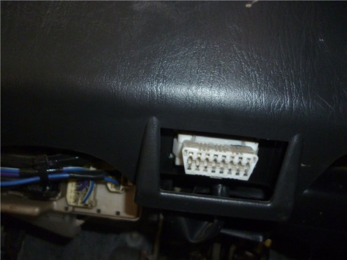
TOYOTA OBD-II diagnostic connector
1 none2 J1850 Bus+3 none4 Body ground5 Signal ground6 CAN-High line, J-22847 K-line diagnostics (ISO 9141-2 and ISO/DIS 14230-4)8 none9 none10 J1850 Bus-11 none12 one13 TC – Timing Check – Output for disabling SOP adjustment for checking the base angle (?) or output for reading slow self-diagnosis codes ABS14 CAN-Low line, J-228415 L-line diagnostics (ISO 9141-2 and ISO/DIS 14230-4)
16 Power supply +12V from battery
Location in cars
Every car owner should know this:
|
Tips for drivers - how to properly heat seats. This article describes the sequence of self-installation of heated seats in the salo... |
|
A good quality car stereo is no longer considered a luxury. And if it is important for the driver to listen to music in high quality, or moreover, to listen to the operational situation on... |
|
For diagnostics and self-repair of Ford cars, 5 diagrams of computer diagnostic connectors for FORD are provided. The immobilizer uses K-Line to communicate with the ECU and is included in... |
Source: http://electroshemi.ru/news/diagnosticheskie_razemy_toyota/2013-12-29-39