Dpkv - what is it, signs of malfunction
The crankshaft position sensor is a fairly important device in a modern injection engine . Each driver must be able to correctly determine its malfunction, since if the sensor fails, the engine will simply stop. It's time to find out about DPKV, what it is, as well as its signs of malfunction.
What does DPKV consist of?
Before considering malfunctions of the crankshaft sensor, it is necessary to carefully study its structure and purpose. It is worth noting that such a device is designed for synchronous operation of the injection system, as well as the ignition.
The design of the sensor is quite simple: it consists of a nylon body, which is carefully wrapped with copper wire. All this is mounted on a core made of steel. Copper wire is coated with special insulation in the form of enamel, the role of which has always been played by compound resin.
When the engine starts running, the sensor reads the angular position of the crankshaft and sends the necessary signal to the electronic engine control unit. Thus, he makes the necessary calculations, and then decides at what time intervals it is necessary to supply this or that portion of fuel.
If the crankshaft position sensor malfunctions, the system stops receiving all the information it needs, which means the spark will not fire at the right times, and the injector will simply stop. Thus, the engine will stop without being able to start again.
What are the signs of a malfunction?
Before the worst happens, trouble can be seen in advance. To do this, you should pay attention to the behavior of your engine:
- A strong detonation of the engine appeared, even if it had already accelerated . Detonation is a rather loud ringing sound when the engine is running.
- The engine is completely unstable at idle . There are times when it simply stalls or doesn’t even start. It is a fairly serious and common problem, which is very difficult to identify, since it can be confused with other faults.
- Deterioration of dynamic characteristics . The speedometer will immediately notice that the car has begun to accelerate much more slowly. Many experienced drivers call this well-known phenomenon “stupid acceleration.” However, there may be another malfunction, for example, a broken air sensor or a clogged fuel filter.
- Engine speed becomes unstable . Moreover, this is beyond any control; the motor can suddenly increase or decrease them. This can be attributed to the second point.
How to start an engine with a faulty DPKV
How can you check the functionality of the sensor?
Finding out the status of this device is quite simple. It is not necessary to have very extensive knowledge in electrical engineering, it is enough just to have the necessary device and a basic understanding of the principle of its operation.
First of all, the DPKV must be removed and carefully inspected . Sometimes such a check provides answers to many questions, and a simple cleaning of the element can solve a rather serious problem.
In addition, damage to the contact group cannot be ruled out, which can create certain troubles affecting the operation of the engine.
However, the most common “dialing” is considered a more productive method of verification.
Video on the topic
Source: https://365drive.ru/remont-avtomobilej/dpkv-chto-eto-priznaki-neispravnosti-pri-rabote-dpkv.html
Checking the crankshaft sensor for serviceability
The dynamics of a car is something for which many fans of fast driving are willing to pay a lot of money. There are some people who are not interested in anything else in the car. And imagine the disappointment when you paid a considerable amount of money, and after a few years your car began to eat its tail.
There are dozens of systems in a car, the failure of which can have a bad effect on its dynamics. In this regard, experts recommend starting your check with the simplest and most accessible ones.
For example, before making claims on your engine, check the crankshaft sensor, or rather, its position.
Crankshaft sensor
The crankshaft position sensor is often also called a synchronization sensor, since it is directly involved in synchronizing the fuel supply and ignition timing by transmitting electronic pulses to the vehicle's electronic control unit.
Thus, if its position is violated, then your engine has every chance of not starting or starting on the tenth attempt. In some situations, this malfunction first gradually makes itself known, reducing engine power.
Signs of breakdown
The video shows a malfunction of the crankshaft sensor on a Hyundai Accent:
Like any other part, the crankshaft sensor has its own list of signs indicating its failure:
- Idle speed is floating.
- The speed decreases and increases without driver intervention.
- Significant reduction in power.
- Engine detonation appears at high speeds.
- The engine does not start completely or partially.
In any case, at the first manifestation of the above symptoms, try to check the position of the synchronization sensor. Sometimes the problem is a malfunction of the fuel pump or spark plugs, but in such situations a special light on the dashboard lights up - CHECK.
In order to check the position of the synchronization sensor, there is no need to contact a specialist; you can easily do it yourself, which means it’s free. This can be done in several ways, each of which requires a specific device.
The video shows how to check the crankshaft sensor for a malfunction:
So, we present to your attention the two most common ways to check the crankshaft sensor. One of them is simple, since it uses only one instrument, and the second is more global and requires several measuring instruments.
As you understand, to check the synchronization sensor, you must first dismantle it. Do this only after you have fixed its original position on the motor using ordinary marks.
Once you have the sensor in your hands, check it for visible damage. Make sure there are no problems with the contacts, core, or contact block anywhere. It is always easier to detect a malfunction if the device is clean . To do this, wipe it and the contacts with a cloth soaked in alcohol or gasoline.
Before removing the crankshaft sensor, evaluate the distance between its core and the timing disk. According to the regulations, it should be 0.6–1.5 mm.
The video shows how crankshaft sensor malfunctions affect engine performance:
Having completed all the above described manipulations and not finding any problems, check the electrical circuit. Very often, this is where the causes of device malfunctions lie.
Use an ohmmeter to check the sensor winding resistance. If the device is working properly, its resistance is in the range of 550–750 Ohms. The operating instructions for your car will allow you to eliminate measurement errors. It indicates the exact parameters of such measurements. If the winding resistance differs from the standard, then you need to replace the crankshaft sensor.
Global check
For such a check, take several devices at once:
- digital voltmeter;
- inductance meter;
- network transformer;
- megohmmeter
Measurements will be most accurate if the air temperature reaches 20–22 °C. Under other conditions, some deviations and errors of the devices are possible.
As you already understood, you need to use an ohmmeter to determine the resistance value of the synchronization sensor winding. An inductance meter will tell you what the inductance of the fixture is. For a working one, it ranges from 200 to 400 mH.
The insulation resistance can be checked using a megger. In this case, the voltage should be 500 V. The absence of insulation problems will be indicated by a figure of approximately 20 MOhm.
Sometimes the fault lies in the magnetization of the crankshaft sensor. This happens when it is being repaired. A network transformer will help get rid of this problem. It is with its help that you will demagnetize the disk.
So, after measuring all the necessary parameters, you can easily determine whether your timing sensor is working correctly. Remember that in some cases, only replacing the crankshaft can restore the car to its former power.
It is worth noting that at the service station its performance is checked using a special program and an oscilloscope. In this case, the device is not removed. An oscilloscope allows you to monitor the formation of a signal that indicates problems.
Everyone independently chooses which verification method is suitable for their car. The main thing is to carry it out carefully and carefully; perhaps you should even invite your car enthusiast friend with you. In our opinion, the second method is the most profitable and effective, but to carry it out you need to have various devices on hand, which not everyone has in their garage.
Source: http://365cars.ru/remont/datchik-kolenvala.html
VAZ 2112: crankshaft sensor - malfunctions and replacement
Crankshaft sensor VAZ 2112
In the design of the VAZ 2112 engine, the crankshaft position sensor is an electromagnetic sensor through which the operation of the ignition system and fuel injectors is synchronized in the fuel injection system.
Therefore, DPKV is actually the main one; without it, the operation of the entire fuel injection system becomes impossible. When a crankshaft sensor malfunction occurs on a VAZ 2112, this inevitably leads to unstable engine operation.
It is very easy to identify faults and replace the DPKV by reading our article.
Operating principle and location
It should be noted that malfunctions of the crankshaft sensor (controller here and further in the text) are rare, however, when going on a long trip, it is better to have a spare working sensor, if the DPKV fails, then further driving of the car most often turns out to be impossible.
Let's move on to the principle of operation:
- The toothed pulley of the electric generator drive is made in the form of a disk with 58 teeth around its circumference, located every 6 degrees
- In order to generate a speed synchronization pulse for the injector, two teeth are specially missing on the pulley
Scheme of operation of a sensor with a pulley
- The car is equipped with either an all-metal pulley or a pulley with a damper (rubber insert)
- All-metal pulleys are practically not subject to wear during engine operation.
- You only need to ensure that there is no dirt or foreign particles between the teeth
- If the pulley has a damper, then you need to monitor the condition of the damper; damage to the damper will definitely lead to problems with engine operation
- When performing repair work, you must be careful not to subject the pulley to deformation; deformation can lead to interruptions in the operation of the motor.
- You can visually check the condition of the generator drive pulley by looking through the front right wheel arch
- In our case, the engine has an all-metal pulley
- If a malfunction occurs in the crankshaft position controller, or the drive pulley of the electric generator, as well as the timing drive, the computer may record an error, which will be reflected by the “CHECK ENGINE” light coming on.
- And enter the corresponding code “35” or “19” into the error buffer
The following symptoms characterize the occurrence of malfunctions of these elements:
- Unstable engine speed at idle
- There is a spontaneous decrease or increase in engine speed
- Complete stop of the engine and complete inability to start the engine
- Noticeable decrease in engine power
- The appearance of detonation under standard dynamic loads, as well as misfiring (motor trouble)
The question remains for the VAZ 2112 where the crankshaft sensor is located, the answer is - it is located on the oil pump cover.
Location of the crankshaft position controller
How to determine that the crankshaft position sensor on a VAZ 2112 is broken, and not something else:
- A strong decrease in the dynamic characteristics of the engine while the car is moving (there can be many reasons for this problem, but this is the kind of malfunction that the computer will report, which, having detected the problem, will light up the “check engine” light on the dashboard)
- If the engine speed spontaneously “walks” (decreases or increases)
- Idle speed instability
- The appearance of detonation in the engine under dynamic load
- The engine cannot be started
Here are the main characteristic symptoms of a breakdown of the crankshaft speed controller, or a generator drive pulley, or timing problems. From the very beginning, you need to understand how you can perform a high-quality test of the performance of the DPKV yourself and be one hundred percent sure that everything is in order with it. Why should this check always be performed first?
Everything is simple here, even without looking at the fact that the controller is located in an inconvenient place, our instructions for checking its functionality will help you complete everything quickly enough. And after checking it will be clear whether the controller needs to be changed.
Performing a check
You can determine the serviceability of (DPKV) in several ways.
Each method requires the use of special devices. Most often, three main methods are used to check the performance of the crankshaft speed controller, let's look at them in order:
- Listening to the advice of professionals, before checking it is always necessary to remove it by unscrewing the fastener of the VAZ 2112 crankshaft sensor, do not forget to fix its initial position on the engine with marks
- Everyone understands that it is necessary to inspect it after removal
- Visual inspection makes it possible to detect external damage on it
- And understand the condition of its contact block and the core of the contacts themselves
- Dirt should be removed from it using alcohol or gasoline.
- The contacts at the crankshaft controller must be clean
- During the removal process, it is necessary to clearly mark the distance from the controller core to the synchronization disk
- Typically it varies from 0.6 millimeters to 1.5 millimeters
- If there are no visible problems, you need to move on to identifying hidden problems in the electrical circuit of this device
Diagnostics using an ohmmeter
To measure the resistance of the crankshaft controller winding, you can use an ohmmeter (multimeter):
- A normally operating controller will show values ranging from 550 Ohms to 750 Ohms
- This test with a multimeter consists of measuring the resistance of the controller inductor
- If the coil is damaged, the sensor characteristics are displayed on the resistance first
- We set the required range and check the resistance with tester probes at the terminals
- This check is the simplest and most basic, so it does not give 100% confidence in the correctness of the diagnosis.
- In order not to doubt the actions being performed, carefully study the instructions included with your car before starting work.
- If the obtained measurement indicators do not fit into the declared interval, then it is necessary to replace the crankshaft speed controller
The second method of checking the performance of the DPKV is more labor-intensive and to implement it, you will need the following devices:
- Megger
- Inductance meter
- Network transformer
- Digital voltmeter
For the reliability of the obtained indicators, the air temperature is important, preferably 20-22 degrees, we do the following:
- We measure the winding resistance with an ohmmeter, as before
- Then we move on to checking the winding inductance using a special meter
- The inductance of a working meter is in the range of 200-400 MegaHertz
- Next, we’ll use a megger and move on to checking the insulation resistance
- At a voltage of 500 Volts, this parameter should not exceed 20 MegaOhm
- If accidental magnetization of the synchronization disk occurs during sensor repair, then you should definitely demagnetize it using a network transformer
- Having analyzed all the data obtained as a result of these measurements, we can draw a conclusion about the performance of the crankshaft controller or the need to replace it
- When installing a new or old device in its place, do not forget to pay very close attention to the marks left during dismantling, remember the need for a distance of 0.5-1.5 millimeters from the controller core to the synchronization disk
DPKV check diagram
- The third method of checking the crankshaft speed controller is the most accurate of all and is used, as a rule, at professional stations
- Since it requires an oscilloscope and a special program
- This method does not require removing the device from the engine.
- Since it allows you to see the signal formation on the screen
- Therefore, the presence of a digital oscilloscope helps specialists to effectively identify various problems that have arisen in the injection system
Diagnostics with an oscilloscope
The third method is not available to everyone, since oscilloscopes are not available everywhere and not everyone can be satisfied with the price:
- To get correct readings, you need to take the black clamp of the oscilloscope, the so-called “crocodile”, and connect it to the ground of the motor of the machine being tested
- The probe probe is installed parallel to the signal output of the sensor (controller connector - terminal A)
- And the second connector of the probe from the oscilloscope must be connected to the analog input No. 5USB of AutoscopeII
- These actions must be performed in order to see on the screen voltage oscillograms at the input of the crankshaft position controller
- Then you need to enable the oscillogram display mode called “InductiveCrankshaft”
- Only now can you start the car
- When it is impossible to start the engine, then it is necessary to rotate the engine with the starter
- If the signal from the crankshaft position controller is received, but the signal output parameters do not match the nominal ones. Then the car may twitch, and it may be difficult to start its engine, failures
- Violations of the characteristics of the outgoing signal from the crankshaft controller indicate existing malfunctions of either the controller itself or the drive disk and possible breakage of the teeth
- The true assumption about the nature of the malfunction becomes clear when considering the waveform on the oscillogram of the voltage pulses, which are recorded at the output of the crankshaft position controller
And so you have become familiar with all three possible methods for checking the crankshaft controller (sensor):
- Using an Ohmmeter (measuring winding resistance);
- Using a tester (checking insulation resistance and inductance);
- Using an oscilloscope
It is up to you to decide which methods to check according to your capabilities. The main thing is to be objective in obtaining results, careful and very attentive when checking
Replacing the sensor
To remove the crankshaft position controller you will need a “10” key.
The removal procedure is as follows:
- Turn off the ignition and disconnect the sensor connector
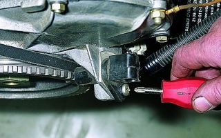
- Unscrew the bolt securing the sensor using the “10” key, photo below
We unscrew the DPKV using the key “10”
- Remove the DPKV from the oil pump cover bracket
- We install the tested or new controller in place in the same way
- Brand of crankshaft position sensor VAZ 21124 according to catalog 2112-3847910
That's all, the video will help you further understand the verification.
Source: http://MasteraVaza.ru/elektroprovodka-i-elektrooborudovanie/datchiki/vaz-2112-datchik-kolenvala-1124
Symptoms of a faulty crankshaft sensor or how to prevent breakdown
The crankshaft position sensor (CPS) device includes:
- Nylon frame;
- Steel magnetic core;
- winding made of thin copper wire;
- Insulation (enamel or resin).
The sensor is designed to create synchronized operation of fuel injectors and the ignition system. Faulty operation of this element leads to unstable operation of the fuel supply or to its absence, fraught with stopping the engine and the inability to start it .
The operation of the sensor allows the computer (microcontroller) to determine the position of the pistons in the cylinders. The crankshaft has a gear with two missing teeth.
During the movement of the shaft, the teeth of the wheel pass near the sensor, thereby distorting its magnetic field and pulses are formed in the inductance coil of the sensor. The absence of two teeth is the starting or zero point for the computer to determine the initial position of the crankshaft.
The computer counts the number of pulses that come from the sensor and determines what position the crankshaft is in and, based on the position of the crankshaft, calculates the time for the fuel injectors and ignition system to fire.
Location
This element is located in the bracket, the bracket itself is located in the area of the generator drive pulley. Installed with a small gap of 1-1.2 mm near the toothed pulley.
The place in which it is located is very inconvenient for penetration. And for convenience, a small (up to 70 cm) wire with the necessary connectors is connected to it.
In order to set the position, you need to adjust the washers between the mounting socket of this element.
Main symptoms of a malfunction
There are a number of vehicle operating errors that relate to the malfunction of this measuring device. In general, when this element fails, a red light (Check engine) lights up on the instrument panel. This way you can understand that it is faulty. So what are these symptoms?
- A sharp decrease in vehicle power, which can be determined even without special instruments;
- An arbitrary decrease or increase in engine speed occurs;
- During dynamic load, detonation occurs in the engine;
- The engine does not start when turning the key;
- When the car is idling, unstable engine speed occurs;
- No idle speed.
To check the performance of the meter, it is not necessary to contact a specialist. You can perform this action yourself. This can be done using several options; they differ only in the use of different devices. Simple method.
Before checking, you need to dismantle the device, and before removing it, you need to make marks of its original position. It is also necessary to check the gap between the core and the synchronization disk; its value should approximately be in the range from 0.6 to 1.5 mm. After removing, carefully inspect it for visible mechanical damage.
To get a better look, the meter and its contacts need to be wiped with a cloth soaked in alcohol. If during inspection no mechanical damage was found, then you need to start studying the electrical circuit. You need to check the winding resistance on the coil using an ohmmeter.
If the device display shows numbers in the range from 550 to 700 Ohms, this means that the sensor is correct. If there is a different value or does not respond to the test at all, this is a sign that the crankshaft position meter is faulty. Deep check. The winding resistance, insulation resistance, and magnetization of the sensor are checked.
For such a check you need to use: a network transformer, a megger, a digital voltmeter, an inductance measuring device. It is important to know that measurements will be more accurate if they are carried out at an air temperature of not 20º C. If the sensor is working, you need to check the pulley. It may not fit tightly on the shaft, which leads to incorrect pulses from the sensor.
Or the reason is in the wheel with teeth. One or more teeth may have broken off. But it is unlikely that things will come to a deep check. Basically, in order to understand whether the device works or not, it is enough to test it with an ohmmeter.
Video “Crankshaft Position Sensor”
In the recording, the expert talks about the crankshaft on a 2003 Scoda Oktavia.
Source: http://MineAvto.ru/remont/dvigatel/simptomy-neispravnosti-datchika-kolenvala-68.html
Crankshaft sensor - where to find it and how it works
You can easily find two or three dozen sensors in any car. However, the crankshaft position sensor is of particular importance in cars equipped with injection engines.
Its abbreviated name in the technical literature is DPKV, although other options may occur.
This is the only sensor that is designed not only and not so much to receive information, but to ensure engine operation.
If this device fails or is disabled, you will never be able to start the engine. And, to prevent this from happening, together we will try to find the answer to the questions about what the crankshaft sensor is needed for, what is its structure and operating principle, and what to do in case of a malfunction? What does the crankshaft sensor do?
The engine operates stably only if the processes of formation of a combustible mixture, ignition and exhaust are clearly synchronized with each other.
In injection engines, where fuel is injected into the combustion chamber, this is much more difficult to do than in carburetor versions.
Obviously, high-precision electronics must give the “command” to supply the fuel-fuel mixture to the cylinders (each) and ignite the spark plug.
Working principle of the crankshaft sensor
Crankshaft sensor overview
The driving force that forces the electronics to supply fuel and spark in a timely manner is an electromagnetic pulse.
The sensor itself is located in close proximity to the toothed rim of the generator pulley, mounted on the end of the crankshaft. Teeth with gaps are made exclusively for the needs of the sensor.
The nature of the appearance of the pulse, which provides a reference for further cyclic synchronization, can be different:
- inductive - the synchronization tooth passes through the magnetic field of the sensor;
- Hall effect – the magnetic fields of the disk and sensor interact with each other;
- optical – triggered when the light flow is interrupted.
Preference is given to the first version, since this operating principle allows it to work without additional energy sources, and in addition to using a sensor to measure the shaft speed and vehicle speed.
Where is the crankshaft position sensor located and how does it work?
Checking the crankshaft position sensor
The location of the crankshaft sensor depends on the make or model of your vehicle. In any case, you need to look for it in the immediate vicinity of the crankshaft pulley. Typically two mounting options are used:
- on the oil pump housing;
- on a separate metal bracket.
Regardless of where it is located, the design of the crankshaft sensor in different cars is almost the same. By design, it is an ordinary electromagnet with a core and windings. A fairly simple design solution suggests that it should not break.
In reality, the sensor rarely fails. The electromagnet is securely fixed in a plastic case, from which an electrical cable in elastic insulation extends, ending with a terminal connector.
The minimum of components and features of the device do not allow the sensor to be repaired - it cannot be disassembled. If it breaks, it is simply replaced.
How to replace the crankshaft speed sensor
Experienced drivers strongly recommend having a spare DPKV in your car repair parts kit. It does not take up much space and is inexpensive; however, in the event of a breakdown, you can start the engine only after replacing it. The replacement procedure is quite simple:
- Having established the location of the sensor, it is necessary to turn off the power supply by removing the contacts from the battery;
- the sensor wire connector is disconnected from the electronic control unit (the wire can be disconnected on the sensor itself);
- The sensor is removed after unscrewing the mounting bolt.
Accordingly, installation of the part must be done in the reverse order of removal. During installation, it is important to maintain the gap between the end of the sensor and the pulley teeth.
Source: http://CarTore.ru/3554-datchik-kolenvala-ustroystvo.html
Crankshaft position sensor: malfunctions, check, replacement
The crankshaft position sensor is the only vehicle electrical equipment sensor that, if faulty, will prevent the engine from starting.
Its impulse determines the time of fuel injection into the intake manifold and the moment of spark formation in gasoline engines.
For four-cylinder engines, its impulse coincides with the moment when the pistons of the first and fourth cylinders pass top dead center, which is why it is often called the TDC sensor.
Types of DPKV
Based on their operating principle, these devices are divided into the following types:
- Inductive (magnetic) crankshaft position sensor. It does not require power to operate. Devices of this type consist of a core and a coil of thin enameled copper wire wound around it. This crankshaft position sensor is installed near the generator drive pulley, which has projections similar to teeth with a flat top, so that when a tooth passes near the core, a pulse of electrical voltage is induced in the coil. To increase noise immunity, the teeth are made at equal intervals along the entire perimeter of the pulley, and in the area corresponding to TDC of the first and fourth cylinders, there are no two teeth in the sequence of protrusions. Thus, the crankshaft sensor produces a sequence of pulses, and the TDC signal is the absence of two pulses in the sequence.
- Crankshaft position sensor based on Hall effect. Consists of a semiconductor sensing element and an integrated amplifier. Requires power to operate. The Hall effect is the occurrence of transverse voltage in a conductor with an electric current placed in a magnetic field.
Symptoms of the malfunction
The most common signs of DPKV malfunction:
- The engine does not start.
- Shots into the muffler and air filter when trying to start the engine.
- Engine instability.
- The motor doesn't pull.
- Detonation under load.
Location
If there are signs of a malfunction, then in order to start checking the DPKV, you need to know where the crankshaft sensor is located.
Most often it is located on the front of the engine next to the generator drive pulley or on the clutch housing opposite the flywheel.
In the second case, a pin is pressed into the flywheel; when it passes near the device, the crankshaft position sensor generates a TDC pulse.
Examination
- Diagnosis of a malfunction of the inductive sensor located on the front begins with an external inspection of the pulley. For example, on cars of the VAZ family, the pulley is made of two parts - an inner disk and an outer ring with a track for a poly-V-belt drive and synchronizing teeth. Between them there is a damping layer of rubber, which holds them together. Often there is a case of destruction of the rubber layer, while the outer ring remains put on the inner disk, but does not rotate with it, and the device does not produce a TDC synchronizing signal due to such a malfunction of the pulley. In this case, the engine, of course, does not start. The possibility of loosening the pulley fasteners cannot be ruled out either. The symptoms of this malfunction will be identical to the previous one. Also make sure that the sensor itself is securely attached. Now unscrew the DPKV and carefully inspect it. Its core should not have any traces of contact with the pulley, and the body should not have cracks or chips. If no traces of mechanical failure are found, check the integrity of its winding with an ohmmeter, since most often it fails due to a break in the winding or connector. The resistance of its winding is usually about 600 Ω. With a significantly lower value, an interturn short circuit is assumed; this event is unlikely, but possible.
- How to check a crankshaft sensor based on the Hall effect. This can be done without removing it from its place. Before checking, make sure that it is receiving power and there is no break in the ground wire. Connect a voltmeter with a measurement limit of about 15 V to the output of the device and to the ground of the car, observing the polarity. Turn the ignition on and turn the engine crankshaft manually using a ratchet wrench. The voltmeter reading should vary from 0.4 to 8 V (ideally from 0 to 12 V).
Replacing the sensor
The process of replacing this unit is simple. The only thing you need to pay attention to is setting the gap between it and the synchronization teeth necessary for normal operation of the unit.
Usually its value ranges from 0.5 to 1.5 mm, but it would be more correct to clarify this parameter for your internal combustion engine. To measure the gap between the sensor and the pulley, you will need a set of flat feeler gauges.
In this case, it is measured quite simply - you need to find the probe moving in the gap with slight pinching and look at the markings on it.
If the sensor is installed in the clutch housing, a caliper will be needed to set the gap. In this case, the gap is determined somewhat more difficult. Rotate the flywheel so that the pin that forms the pulse in the sensor is visible in the hole for installing the sensor.
Using a caliper, measure the distance to it from the sensor mounting plane; we will designate it as X. On the sensor, measure the distance from the end of the core to the mounting bracket; we will designate it as Y.
The gap that will result when installing the sensor without adjusting washers, let's denote it Z, will be equal to X-Y.
If it is less than required, then under the sensor bracket you need to place washers whose thickness is calculated as Zreq - Z where Zreq is the required gap, but if it is a little more, which is unlikely, but still, then it is necessary to grind off the bottom of the bracket to a thickness equal to Z - Zreq.
Source: http://AutoLirika.ru/teoriya/datchik-polozheniya-kolenvala.html
Checking the crankshaft sensor
The operation of the injection engine, including the fuel supply and ignition systems, is subject to the readings of the crankshaft position sensor (CPS). The sensor monitors and reports crankshaft position data to the injector controller by generating short bursts of pulses.
How does DPKV work?
The operation of the sensor is based on the Hall effect, due to which an electromotive force (EMF) pulse is formed in the inductor when passing through a magnetic field.
The magnetic field changes when the crankshaft signal gear, which has teeth cut into it, passes the sensor.
The gap that takes the place of two teeth gives the controller a signal that the top dead center (TDC) of the first cylinder is approaching and gives a command to start the countdown; small teeth report the position of the crankshaft in real time.
DPKV malfunctions
The most common malfunctions of the crankshaft sensor:
- damage to the body;
- inductor break;
- interturn closure;
- oxidation of contacts.
Malfunctions not related to the sensor, but affecting its operation:
- damage to one or more gear teeth;
- gear magnetization;
- changing the distance between the sensor and the gear.
If the DPKV housing is damaged, water and dirt may enter it. This often leads to winding breakage and interturn short circuit. If the winding is broken, then no EMF is formed in it and it is impossible to start the engine.
During an interturn short circuit, an EMF is formed, but its strength and shape do not correspond to the calculated ones, as a result, errors occur that change the operating mode of the injector. Such errors appear, if not constantly, then quite often, so a sudden change in engine operation should alert the driver.
When the contacts of the block and the terminals of the wires that are connected to the DPKV are oxidized, the signal disappears without warning and often returns unexpectedly.
If repairs or diagnostics of the DPKV are performed incorrectly, the gear may become magnetized, resulting in a change in the shape and voltage of the EMF.
Errors in engine maintenance can lead to the loss of one or more teeth by the gear, as a result of which the entire algorithm of the injector operation is disrupted, because two “zero” points appear from which it is necessary to count.
Incorrect installation of the DPKV after diagnosis or repair leads to a change in the distance between the teeth and the sensor, which greatly affects the shape and voltage of the EMF.
Video - Hall sensor diagnostics
How to check DPKV
There are four testing methods that allow you to determine the condition of the DPCV and gear, as well as their effect on the operation of the injector. Each method requires its own equipment, and the accuracy of the test also varies.
On front-wheel drive vehicles with a transverse engine, to check the DPKV, you will need to remove the wheel on the sensor side. On front-wheel drive vehicles with a longitudinal engine arrangement, as well as on rear-wheel drive vehicles, the check is performed either from above, through the engine compartment, or from below.
In the second case, you will need to raise the front of the car. For information on how to do this safely, read the article (replacing and restoring shock absorbers).
To do this, it is necessary to clean the DPKV, the installation site and the signal gear. Then mark the position of the sensor and remove it. After dismantling, the sensor is washed and wiped with a clean cloth moistened with alcohol or gasoline. After cleaning the DPKV, it is inspected looking for cracks, scratches, dents and other damage. If any damage is detected, the sensor must be replaced.
- Checking with a tester
This check allows you to evaluate the approximate condition of the sensor, but does not take into account the influence of gears and other factors. To check, remove and clean the sensor as described above, then measure the resistance with a tester. Depending on the DPKV model, the winding resistance of a working sensor is from 600 to 900 Ohms.
But such a test does not determine the interturn short circuit, unless at least a quarter of the winding rows are closed. After this, connect the tester in millivoltmeter mode to the sensor outputs and run a steel screwdriver near the core several times.
A working sensor will show voltage surges of up to 0.1 - 0.3 volts (depending on the model, the weight of the screwdriver and the speed of its movement).
- Testing with an inductance meter
Often the inductance measurement mode is found on digital testers (multimeters). If such a tester does not exist, you must purchase any inductance meter with an accuracy of 10 milliHenry (mH). Depending on the model, normal inductance is 200 – 400 mH.
- Checking with an oscilloscope
To check, you will need a digital oscilloscope with automatic voltage and frequency control and an input resistance of at least 100 kOhm or a digital scanner for injection cars, with a visual indication mode.
Connect the oscilloscope's ground to the car body or the negative terminal of the battery, and the signal input to any DPKV pin. Turn on the ignition and start the engine. Observe the sensor's performance using an oscilloscope.
As engine speed increases, the voltage at the DPKV output should also increase. At 4 - 5 thousand revolutions the voltage should exceed 200 volts.
Carefully monitor the oscilloscope readings; for one revolution of the crankshaft there should be only one dip, corresponding to TDC of the first cylinder. When the engine speed changes, the oscilloscope will adapt by changing the input voltage mode, but when operating at the same speed, the deviation in the voltage value should not exceed 5 percent.
A more serious deviation indicates magnetization of the signal gear. Two or more dips in one cycle indicate that the gear has lost one or more teeth. Voltage readings constantly changing between 10 and 15 percent indicate that the sensor is poorly secured and vibrates, or there is runout in the crankshaft signal gear.
Source: http://VipWash.ru/kolenval/proverka-datchika-kolenvala