Design and principle of operation of the carburetor
Now all modern gasoline engines are equipped with an injection power system. Due to the fact that the injector is more advanced, it has practically replaced the carburetor in vehicles. But there are still a large number of cars on the roads, the engines of which are equipped with a carburetor system.
The carburetor is the main component of such a system, and its main task is to prepare the air-fuel mixture in the required proportion for its subsequent supply to the combustion chambers of the engine.
There are three types of carburetor systems in total, one of which, the bubbling type, is not used at all, and the other two, which include needle-membrane and float carburetors in the design, are still quite applicable and can be found on a wide variety of equipment.
Of the last two, only a float-type carburetor was used in vehicles. The needle-membrane type can be found on chainsaws, lawn mowers and even on aircraft.
The float-type carburetor is a single unit included in the power system. During the use of such a system on cars, a large number of carburetors have been developed, with different design features, but they all function using the same principle.
The simplest float carburetor consists of two chambers:
- float;
- and mixing.
The first task is to dose the fuel and maintain it at a certain level. Thanks to this chamber, a stable supply of gasoline is ensured under different engine operating conditions.
Structurally, it is very simple. Inside the assembly there is a cavity with a float placed in it, connected to a needle-type valve, which is located in the gasoline supply channel from the gasoline pump.
As fuel is consumed, the float lowers, and with it the valve, as a result the channel opens and gasoline is pumped into the cavity.
When the required level is pumped, the float together with the valve rises up and completely blocks the channel.
Video: Carburetor design (Especially for AUTObabies)
The second chamber ensures mixing of fuel into the passing air stream. For this purpose, a diffuser is installed in it - a specially narrowed section of the chamber. Thanks to this diffuser, the air passing through it is significantly accelerated.
These two chambers are connected to each other by a sprayer. The side that is installed in the float chamber is additionally equipped with a nozzle - a special insert with a through hole of a certain diameter. Its task is to ensure the supply of a strictly defined amount of gasoline. The second end of the sprayer is led into the diffuser.
It all works like this: during the intake stroke, the piston moves downward in the cylinder, creating a vacuum. Because of this, air is sucked through the air intake with a filter installed in it. This intake is located on the carburetor so that the flow passes through the mixing chamber.
The movement of air during acceleration in the diffuser ensures the formation of a vacuum in the spray tube, due to which fuel begins to flow out of it and mix into the passing flow.
Regulation of the mixture supplied to the cylinders is ensured by a throttle valve, which is installed behind the diffuser. By blocking the channel through which the air-fuel mixture moves, the speed of air movement is regulated. It is this valve that the driver acts upon by pressing the accelerator.
The carburetor design involves another damper - an air damper. If the throttle regulates the supplied amount of the ready-made mixture, then the second damper shuts off the air supply. And since a vacuum is still created in the cylinders when the engine is running, the mixture turns out enriched, which is characterized by an increased fuel content.
What else is included in the design?
But this is a simplified carburetor diagram. In reality, everything is much more complicated, because the engine operates in different modes during operation, and each of them requires a mixture of the appropriate composition.
Therefore, a modern float-type carburetor has a complex design with a significant number of channels, auxiliary systems and additional equipment. All this allows the carburetor to provide mixture formation in any operating mode.
Therefore, in the design of the carburetor, in addition to two chambers, there is:
- starting system;
- main dosing system;
- idle system;
- accelerator pump;
- economizer;
- econostat;
Each of these components has its own purpose and ensures the supply of a mixture that is optimal in quantity and quality in any mode of operation of the power unit.
1. Starting system
The starting system ensures that a rich mixture is supplied to the cylinders when the engine is started. The main element of this system is the air damper. In domestic carburetors, it has manual control (a choke handle located in the cabin). In foreign analogues, an automatic start system is often found, which independently regulates the degree of opening of the air damper.
At the same time, the starting system is structurally designed to prevent the supply of an over-enriched mixture to the cylinders immediately after starting the engine.
For this purpose, the damper drive is made so that it can open slightly on its own, ensuring a lean mixture.
In addition, it is connected through a rod system to the throttle valve, which allows the carburetor to regulate the degree of opening of these valves during startup and warm-up.
2. Main dosing system
The main dosage system ensures the main supply of the mixture to the cylinder in all engine operating modes. The only thing is that it is not activated when the engine is idling. Its main task is to supply the required amount of mixture (somewhat lean) into the cylinders.
In order to prevent over-enrichment of the mixture in transient conditions, this system compensates for the missing amount of air by supplying from the atomizer not pure gasoline, but an emulsion into which some of the air is already mixed.
To do this, on most carburetors, the fuel, before entering the atomizer, passes through specially made emulsion wells, where pre-mixing is carried out.
The idle system ensures stable operation of the power plant at low speeds when the throttle valve is fully closed. It is a system of channels through which air and fuel are supplied under the throttle valve.
That is, the mixing chamber is not used in this mode, since the XX system produces the required amount of mixture and supplies it to the intake manifold, bypassing it.
Additionally, this system includes another channel - a transition channel, the task of which is to ensure the maintenance of stable engine operation during mode changes from idle to medium speed.
Video: OZONE carburetor. Diagnostics and Repair
The accelerator pump provides the required amount of mixture during sharp acceleration, when the main metering system does not have time to provide this, since it provides normal supply only when the throttle is opened smoothly.
The task of this pump is to briefly enrich the mixture, which avoids “failure” during acceleration. For this purpose, there is a special channel, covered with ball valves and equipped with a membrane, the drive of which is carried out from the throttle.
When you sharply press the accelerator, the balls slightly open the channel, and the membrane squeezes out a portion of the emulsion into a special sprayer installed in front of the diffuser.
Economizer and econostat
The economizer ensures maximum power output from the engine when needed. This is achieved by supplying an enriched mixture by feeding an additional portion of the emulsion into the main sprayer, bypassing the main dosage system.
The ecostat allows the engine to produce maximum power at high speeds. To do this, this element supplies gasoline directly from the float cavity and sprays it in front of the diffuser.
These are the main elements and systems of the carburetor. It also uses a balanced float chamber in its design.
In order for the gasoline in it to be maintained at a given level, a vacuum should not form in the chamber and for this it is connected to the atmosphere.
A balanced chamber involves combining it with the carburetor neck, which prevents contaminants from entering it along with air.
Carburetor adjustment and maintenance
With its complex design, the carburetor does not have many adjustments, and they only concern the idle system and the fuel level in the chamber with the float.
To establish stable operation of the engine at idle, there are two special screws - quantity (air) and quality (fuel). The first is a thrust element that regulates the degree of opening of the throttle to allow air to flow through the gap between it and the wall to create a mixture.
The second screw is a needle screw, installed in the channel through which the emulsion enters the throttle channel. By screwing in and out, the cross-section of this channel changes, and as a result, the amount of emulsion supplied.
The disadvantage of a carburetor is that it has a large number of channels and jets of small cross-section. Therefore, during operation, pollutants that enter along with air and gasoline settle in them and clog the channels and jets.
Therefore, it is important to periodically clean the unit. This can be done manually, with complete disassembly of the unit, washing and purging of the channels.
But recently, special cleaning products have appeared.
Such cleaners are a special mixture that, when entering the channels, ensures the detachment and dissolution of deposits and resins in the channels, after which they enter the cylinders along with the fuel and burn.
But it is worth noting that this product can only remove small blockages. If there is a large amount of deposits, they can only be removed manually.
Source: http://AvtoMotoProf.ru/obsluzhivanie-i-uhod-za-avtomobilem/konstruktsiya-i-printsip-rabotyi-karbyuratora/
Carburetor: design and principle of operation
Until the mid-80s, gasoline internal combustion engines in cars and light trucks were widely equipped with carburetors. Such engines operate on the principle of combustion of a fuel-air mixture prepared in advance by an external device in the engine cylinders.
The specified working mixture consists of droplets of fuel and air. The carburetor is responsible for the process that involves the formation of a mixture of these components in the required proportion for maximum efficiency of the internal combustion engine.
The simplest carburetor is a mechanical metering device.
A little history
Early developments at the dawn of the engine building era used lighting gas as fuel. At an early stage, such engines simply did not need a carburetor. The illuminating gas entered the cylinders due to the vacuum that was formed during engine operation. The main problem with such fuel was its high cost and a number of difficulties during use.
The second half of the 19th century was the period when inventors, engineers and mechanics all over the world tried to replace expensive lighting gas with a more economical, cheaper and accessible type of fuel for the internal combustion engine. The best solution was to use liquid fuel that is familiar to us today.
It is worth considering that such fuel cannot ignite without the participation of air. To prepare a mixture of air and fuel, an additional device was required. Not only that, but it was also necessary to mix air with fuel in the required proportions.
To solve this problem, the first carburetor was invented. The device was released in 1876. The creator of an early model of the carburetor was the Italian inventor Luigi De Christoforis.
In its design and operating principle, the first carburetor had a number of significant differences from more modern analogues. To obtain a high-quality fuel-air mixture, the fuel in the first device was heated, and its vapors were mixed with air.
For a number of reasons, this method of forming a working mixture is not widely used.
Developments in this area continued, and a year later, talented engineers Gottlieb Daimler and Wilhelm Maybach created the design of an internal combustion engine that had a carburetor operating on the principle of fuel atomization. This device formed the basis for all subsequent developments.
Modernization
The main direction of further work of engineers was the maximum automation of all mixture formation processes.
The best minds of many companies producing cars and related equipment worked to improve the design of the carburetor.
For this reason, you can find a great variety of simple and complex carburetor models from numerous global manufacturers.
Further development
Carburetors began to be actively replaced by injection systems only at the end of the 20th century. Until this time, the carburetor design was intensively improved. The latest rounds in the evolution of carburetor injection are electronically controlled carburetors.
Such carburetors had several solenoid valves, the operation of which was controlled by a special control device. For example, we can mention the Hitachi carburetor brand.
The design included nearly 5 valves, and the dampers were electronically controlled.
The latest generation of structurally complex carburetors is perfectly demonstrated by the already mentioned Hitachi carburetor model.
This carburetor was installed on Nissan cars in the late 80s and early 90s.
The complexity of this generation of carburetors lies in the large number of auxiliary devices, especially if you compare the Hitachi product with the primitive Solex, which was installed on the VAZ.
Auxiliary devices were responsible for stabilizing the operation of the carburetor in various modes. Such modes and operating features include sudden release of gas, idling during idle time on a car with an automatic transmission, leveling and stabilization of power unit speed after turning on the air conditioning system, as well as many others.
The carburetor of the latest generations, brought to perfection, basically consisted of numerous devices. We will name only a few of them for your reference:
- Outdoor air temperature control system;.
- Intake manifold heater;
- Fuel cut-off valve;
- Mixture enrichment device valve;
- Bimetallic air damper spring in the throttle opening mechanism;
- Fast idle system, etc.;
Such devices belong to the latest “electronic” carburetors. Additional elements in these models were made in the form of separate analog devices. The devices were controlled by simple electronics or operated on the principle of self-regulation (bimetallic spring).
It is noteworthy that simple mechanical carburetors are very versatile devices and can be installed using an adapter on different car models. An excellent example is the same Solex carburetor, well known to domestic motorists.
Carburetor and injector
Further in the history of fuel supply and mixture formation systems, monoinjection (monoinjector) first appeared, and fully electronic injection and high-performance fuel injectors finally replaced obsolete carburetors.
The main advantage of the injector is much more accurate and timely dosing of fuel to obtain the required proportions of the fuel-air mixture.
The emergence and introduction of affordable microprocessors into the auto industry ultimately led to the fact that the need for a complex carburetor and additional devices in its design simply disappeared.
All the functions of the individual elements of the carburetor were taken over by one single control unit (ECU), and simple design devices were installed in the injector design.
It is a mistake to believe that an injector is a more economical solution compared to a carburetor. A well-tuned carburetor demonstrates similar fuel consumption indicators. The popularity of distributed injection is due to the fact that this particular fuel supply mechanism is capable of meeting all stringent modern standards and requirements for the environmental friendliness of internal combustion engines.
The carburetor cannot satisfy such requirements, which is due to its design features and the performance of the jets.
Today, carburetor injection is found only on those engines whose main purpose is the target installation on special equipment. The reason for this decision was the vulnerability of electronic injection systems during harsh operating conditions.
Electronic components and injector modules suffer from increased humidity and contamination, and injectors are sensitive to fuel quality. As an example, it is worth saying that it is definitely better to install a mechanical carburetor on a special vehicle when using it in swamps, which will not burn out.
Such a carburetor can always be easily maintained, cleaned and dried if necessary.
Types of carburetors
As we have already said, the process of modernizing carburetors has generated a large number of types of this device from different manufacturers. All this variety of carburetors can be divided into three groups:
- bubbling;
- membrane-needle-shaped;
- float;
The first two types of carburetors have practically not been seen for a long time, so we will not dwell on these designs. It is more advisable to consider a float carburetor, which can still be seen in various modifications on civilian cars of the 90s era today.
Float carburetor design
The main job of a carburetor is to mix fuel and air. Different models of carburetors carry out this process according to a similar principle. The float carburetor consists of the following elements:
- float chamber;
- float;
- float lock needle,
- jet;
- mixing chamber;
- spray;
- Venturi tube;
- throttle valve;
The float carburetor is designed in such a way that a special line is connected to its float chamber. This line supplies fuel from the fuel tank to the carburetor. Regulation of the amount of fuel in the chamber is carried out through two elements that are interconnected. We are talking about a float and a needle.
A drop in the fuel level in the float chamber means that the float will drop along with the needle. Thus, it turns out that the lowered needle will open access for the next portion of fuel to enter the chamber.
When the chamber is filled with gasoline, the float will rise, and the needle will simultaneously block access to fuel.
At the bottom of the float chamber there is the next element called a jet. The nozzle acts as a calibrator and ensures dosing of the fuel supply.
Through the nozzle, fuel enters the atomizer. This is how the required amount of fuel moves from the float chamber to the mixing chamber.
The process of preparing the working fuel-air mixture takes place in the mixing chamber.
Structurally, the mixing chamber has a diffuser. This element is designed to increase air flow speed.
The diffuser is responsible for creating air vacuum in the immediate vicinity of the sprayer.
This helps draw fuel out of the float chamber and also helps to atomize it better in the mixing chamber. This is the basic design of a simple float carburetor.
Throttle: cold start and idle
The amount of working fuel-air mixture that enters the engine cylinders will depend on the position of the throttle valve. The damper has a direct connection with the gas pedal. But that is not all.
Some cars with a carburetor had an additional device to control the throttle valve. This element is well known to fans of the old “classics” from VAZ. Motorists popularly nicknamed this device “suction”, and the device itself was created for cold starting. The element is made in the form of a special lever, which is located at the bottom of the dashboard on the driver's side.
The lever allows you to additionally control the throttle valve. If you pull the “choke” towards you, then the damper closes. This allows you to limit air access and increase the level of vacuum in the carburetor mixing chamber.
At increased vacuum, gasoline from the float chamber is drawn into the mixing chamber much more intensely, and the insufficient amount of incoming air forces the carburetor to prepare a rich working mixture for the engine. It is this mixture that is best suited for confidently starting a cold engine.
It is worth noting that the first in the entire design to undergo further modernization was the cold start, already familiar to us under the name “suction”.
The simplest carburetors deservedly include the once widespread and popular Solex carburetor, to which the line of classic VAZ cars owes a lot.
The operation of a carburetor engine in idle mode is as follows:
- The carburetor is equipped with special additional air jets. These jets are responsible for supplying a strictly dosed amount of air;
- the air passes under the throttle valve and is then mixed with gasoline according to the working algorithm. In this case, the entire process occurs when the gas pedal is not depressed and released;
This is what the basic device and operating principle of a float-type carburetor looks like.
Strengths and weaknesses of the device
The main advantage of the carburetor is its affordable maintainability.
To this day, there are special repair kits on the market that allow you to return the carburetor to operation quickly enough.
Repairing a carburetor does not require an arsenal of any special equipment, and almost any motorist can repair the device if they have certain skills.
A mechanical carburetor is not so afraid of dirt and water, since their entry cannot completely damage it. This simultaneously conceals both the strength and weakness of the device.
The carburetor needs to be adjusted quite often and must be cleaned compared to fuel injection, but it is more durable than electronic solutions when a number of conditions arise that are considered difficult or even extreme operating conditions.
Additional advantages of the carburetor include its less sensitivity to low-quality fuel, and the cleaning process does not seem difficult. Although the carburetor is a relatively complex device, it is definitely easier to diagnose problems and maintain it compared to a clogged or faulty injection system.
The main disadvantages of a carburetor include the need for regular cleaning and adjustment. The carburetor can present surprises during operation, as there is a dependence on external weather conditions. During winter, condensation can accumulate in the carburetor body and then freeze.
In hot weather, the carburetor is prone to overheating, which leads to intense evaporation of fuel and a drop in engine power.
The last argument against the carburetor is the increased toxicity of the exhaust, which has led to the abandonment of its use on modern cars around the world.
Today, the carburetor is justifiably considered a hopelessly outdated “classic” solution.
Source: http://KrutiMotor.ru/karbyurator-ustrojstvo-i-princip-raboty/
The principle of operation of the carburetor
At first glance, a carburetor may seem like a very complex device. However, a small amount of theoretical knowledge will help you fully understand its operating principle. Which, in turn, will allow you to independently clean and adjust the carburetor. Basic information is sufficient to perform these operations at the proper level.
How does a carburetor work?
Regardless of the model, the principle of operation of the carburetor is similar. Structurally, any carburetor is made according to the following scheme: a channel for creating an air-fuel mixture, in which there is a special calibration hole for air inlet, a float chamber and an outlet for the finished mixture.
When the engine is running, a reduced pressure is created in the intake manifold (the element connecting the power unit and the fuel system) relative to atmospheric pressure. This causes a vacuum to form in the carburetor.
Thanks to this, air is drawn into the carburetor through a special narrowing channel and gasoline is captured from the fuel chamber.
During the process, these ingredients are mixed, resulting in the creation of an air-fuel mixture that ignites in the combustion chamber (combustion chamber) and causes the pistons to move. The amount of fuel in the finished mixture depends on the pressure created in the mixing chamber.
Due to the fact that the chamber is connected to the atmosphere, due to the pressure difference, gasoline rises up, mixing with air. Next, the mixture enters the combustion chamber. Narrowing the passage accelerates the movement of air, which leads to even greater vacuum.
Fuel supply with air
The supply of fuel and air is controlled by the gas pedal; it is connected to the air damper (VD) and the element that closes the float chamber (PC). When the pedal is free, the engine runs at idle speed (XX).
The damper almost completely closes the calibrated air supply channel, and the needle opens the opening in the fuel chamber. The part for covering the float chamber is made in the form of a needle, divided into several parts, each of which has its own thickness.
Thus, the higher it rises, the more fuel is supplied. The air damper works on the same principle; the wider the opening, the greater the flow.
What is carburetor idle speed - XX
Idle speed can be compared to standby mode. It is necessary to consistently maintain the required speed when the car is not moving, so that the engine does not stall. In this case, the air mixture is saturated with the minimum amount of fuel necessary to maintain stable operation of the system.
When the gas pedal is released, the spool needle closes the main gasoline supply channel as much as possible. The air damper remains slightly open. The passage through which gasoline is supplied is located behind the air damper.
The combustible mixture begins to flow through this channel only when there is increased vacuum in the carburetor, which occurs when the air damper is opened strongly. To create an air-fuel mixture at idle, the design provides an additional oxygen supply channel. It has a special element for adjusting the quality of the combustible mixture.
The more the screw is tightened, the more the mixture is saturated with gasoline. The idle speed increases, and vice versa - unscrewing the screw reduces it. Thus, by adjusting this screw, you can achieve optimal options and increase efficiency.
Why is a float chamber needed in a carburetor?
1 – float axis holder;
2 – float tongue;
3 – float
The PC is one of the main elements of the carburetor, which contains fuel. The liquid level in the chamber is regulated and controlled using a special float. There is a needle attached to it.
It closes the channel for supplying the combustible mixture from the gas tank. As the fuel level decreases, the float begins to fall and the needle rises.
When the chamber is filled, the float rises and the level stabilizes.
The carburetor is equipped with an additional suction mechanism for the throttle control. This element is designed for manual enrichment of the mixture. An additional channel is provided for this function; it is smaller than the main one.
The suction mechanism is controlled by a special lever on the dashboard.
First, you need to pull the element completely towards you, thereby opening the damper as much as possible; as the engine warms up, the lever must be gradually returned to its original position.
Carburetor adjustment
Carburetor adjustment can only be done on a well-warmed engine. Regardless of the design, the principle of calibrating the elements is identical.
- Float chamber . Adjustment and control of the liquid level in the container is carried out using a float connected by wire to a needle. The level of required fuel in the chamber is indicated in the operating manual for the specific car model. Check the current indicators, measure the height of the mirror using a caliper. If the level is higher than normal, carefully take the float in your hand and bend it down using mechanical pressure on the wire. If the fuel level is below normal, raise it.
- Setting XX . The optimal number of revolutions at idle is 800-900 units. Screw the mixture quality screw all the way and unscrew it 4-5 turns back. Tighten the quantity screw until it stops and unscrew it 3 times. Turn on the engine, gradually begin to tighten the first screw, in the process the speed should increase and the engine will begin to operate unstable. When the instability begins, start tightening the adjuster until the engine starts to run smoothly again. Finally, adjust the quantity screw.
- Adjusting the jets . Use the choke to close the air damper. The rod shank should be located at the end of the groove of the PU carburetor rod. In case of deviation, it should be corrected by bending the rod. Then you need to remove the cover, and then measure the gap from the edge of the chamber wall to the air intake. The required indicators are indicated in the instruction manual. The adjustment is made using the PU adjusting screw.
Source: http://VipWash.ru/karbyuratory/printsip-raboty-karbyuratora
Carburetor, operating principle and system design diagram, what type and model to choose and what are the differences characteristics
Liquid fuel in gasoline engines cannot ensure the operation of the piston group.
To create torque on the crankshaft, a series of cyclic micro-explosions in the cylinders is necessary, while liquid gasoline simply burns.
When fuel is mixed with air (which contains large amounts of oxygen), a mixture is created that can create a flare that has high kinetic energy.
Automotive carburetors - history of development
At the dawn of engine building, the use of gas became unprofitable.
There was a need to create a device that could, with a high degree of reliability and safety, ensure the formation of a high-quality mixture from gasoline and air.
The operating principle of the first series carburetor was based on the evaporation of fuel vapor. The chamber was heated from an external heat source, gasoline vapors mixed with air due to convection.
The characteristics of such a carburetor did not allow developing more power, so this design did not take root in engine building. For the first examples of cars, it was enough that they just drove; later, the needs of customers grew, and motorsport began to develop. There was a need to create a carburetor that had no restrictions on engine power.
The next generation, invented by German engineers Daimler and Maybach, worked on the principle of fuel atomization. The size of the unit decreased (there was no need to build in a volumetric evaporation chamber with a heating tank), and productivity, on the contrary, increased significantly.
In fact, a vacuum carburetor was created, the design of which is used in modern models. The main technical breakthrough - the transition of fuel into a gaseous state was forced, which gave scope for experiments with performance.
Of course, the design of the Daimler-Maybach carburetor was not similar to modern designs of high-performance vacuum models with a special receiver and control of air discharge.
Carburetor design (typical description for all modifications)
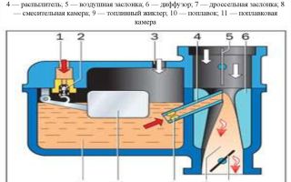
The diagram shows the relative position of the main components:
- Gasoline supply pipe from the fuel pump;
- A float with a needle valve that shuts off the fuel line;
- Jet for receiving fuel from the float chamber;
- Liquid fuel spray nozzle;
- Mixer chamber in which the fuel mixture is formed;
- An air damper that regulates the volume of incoming clean air flow from the filter;
- Diffuser that shapes the direction of air flow;
- A throttle valve that regulates the flow of mixture into the engine intake tract.
How does a carburetor work?
Let's consider the operation of each node.
- Gasoline under low pressure (not to be confused with high-performance nozzles of injection systems) enters the float chamber. It is important to maintain a fuel level in the carburetor that does not exceed the location of the jet. Otherwise, aerosol spraying will not occur in the mixing chamber. For each model, an upper limit for filling the chamber is set, which is mechanically “monitored” by a float with a needle valve. This design was chosen because with a small amount of force the pressure in the incoming fuel line can be maintained. When the limit is reached, the valve closes the inlet; when the level drops, it fills the chamber with gasoline;
- The disadvantage of the design (unfortunately, there is no alternative) is its high dependence on pollution. The needle valve may become stuck closed and the motor will stop running;
- Next, gasoline enters the nozzle. The diameter of this element is strictly regulated; deviations of even hundredths of a millimeter are not allowed. Otherwise, aerosol spraying will not occur at the entrance to the mixing chamber, and the air-fuel mixture will not be formed, and, as already mentioned, the internal combustion engine does not work on liquid gasoline;
- An aerosol of tiny droplets of gasoline emerges from the diffuser, ready to be mixed with air;
- The mixer chamber (actually the carburetor body) is designed to form a gaseous mixture consisting of gasoline vapor and oxygen contained in the air. Gasoline, like air, does not enter the chamber under pressure, but, on the contrary, due to vacuum. When the cylinder moves down, a difference in pressure arises, a kind of vacuum. Due to the specially designed body shape, fuel and air flows are mixed evenly, forming a high-quality mixture;
- The dampers (throttle and air), controlled by the gas pedal, measure the intensity of the air flow and the speed of fuel suction from the nozzle. The engine works more intensely, the crankshaft rotation speed changes along with power and torque.
All carburetor systems must work harmoniously: if one of the channels (nozzles) is clogged, or the position of the dampers is incorrectly adjusted, the formation of the mixture will be disrupted.
Gasoline consumption will increase, power will be lost, the power unit will operate unstably, so all components must be clean, their size must correspond to factory calculations, and adjustment parameters must be adjusted.
There are a number of adjustment screws on the carburetor; the correct specifications are set with their help. The illustration shows an example of an Ozone carburetor.
Each carburetor has instructions for setting parameters. Adjustment can be done independently, or at a specialized service. When operating conditions change (the amount of oxygen in the air, regular load on the car, turning on the air conditioner in the summer, etc.), the settings should be re-adjusted.
What is the difference between a classic carburetor and an electronically controlled device?
The principles of operation of a mechanical carburetor were described above. All settings are set using screws and cannot be changed dynamically during operation. The carburetor circuit is constantly being improved, and new models (some of which are still in production today) have quite a lot of electronics. For example, almost all mechanical models are equipped with a solenoid valve.
The fact is that when the gas pedal is fully released, the throttle valve is closed, and the engine should, in theory, stall.
To operate the internal combustion engine without load (just so as not to start it every time after stopping), an idle system has been introduced. With its help, even with the dampers closed, a minimum volume of gasoline and air enters the housing.
The formed fuel mixture is sufficient to maintain the operation of the power unit without load on the crankshaft.
This parameter requires precise adjustment: if the idle speed is too high, gasoline consumption will increase, and if it is too low, the engine will stall when stopping.
When operating conditions change (temperature, the presence of an air conditioner with air conditioning, additional equipment that puts a load on the generator), the idle speed changes, so an idle speed valve (electric) was installed, which controls the process linearly, depending on the load.
There is no control program; only the power wire goes into the valve. Depending on certain operating conditions, the position of the valve changes.
These are not all electronic systems that can be introduced into the mechanics of the process. For example, all adjustments are made to a control unit, such as an ECU for injection engines.
Such a microcomputer constantly monitors the load parameters on the power unit and can change carburetor settings in real time. Asking yourself the question: “which carburetor is better to install?”, You can consider introducing a modern design into the car.
Unlike traditional carburetors, electronic systems do not require periodic adjustments, but are more expensive and more difficult to maintain and repair.
To provide the electronics with initial data, various sensors are installed on the engine that monitor the motor parameters. Based on the information received, the carburetor actuators are activated.
Types of carburetors by manufacturer - which one to choose?
Everyone has heard the difference of the so-called. Chinese products, and carburetors of famous brands (the list of which includes DAAZ, Solex, and Ozon...). In fact, this is nothing more than prejudice.
A product produced at the factory, in compliance with the technology, and with a quality certificate, will work well regardless of the geography of production.
Only the so-called “no-name” products, collected by peasants from the Middle Kingdom literally with a file on their knees, are of low quality, so when selecting a new carburetor, first of all, focus on the reputation of the manufacturer and the availability of accompanying documentation.
Of course, warranty obligations must also be provided by service centers within accessibility. That is, if you live in Kaliningrad, and the nearest manufacturer’s service center is in Dimitrovgrad, it makes sense to find another copy.
Bottom line
You should not be afraid of this seemingly complex device. The operation scheme is simple and reliable; the key to normal functioning is the cleanliness of all internal elements and correct settings.
Source: https://SwapMotor.ru/ustrojstvo-dvigatelya/karbyurator.html
How does a car carburetor work and how does it work?
Hello, dear car enthusiasts! The purpose of the carburetor in your car is to prepare the fuel mixture - in accordance with the needs of engine operating modes, saturate gasoline with air in the required amount and then supply fuel to the engine cylinders.
A carburetor is one of the complex devices of power supply systems. If car enthusiasts dare to repair it, most of them, as a rule, penetrate no further than the chamber with the float.
Although, as a rule, the cause of carburetor malfunction lies deeper. And then the question arises: repair the carburetor or buy a new one? Those who are inclined to the latter decision should be reminded that the price of some models has become quite significant for the wallet.
While the components for repairing your carburetor will cost many times less. We think that repairing a carburetor with your own hands has a fairly significant economic basis, so let’s still try to disassemble the carburetor.
Carburetor design
Design and operation of the carburetor - video
The schematic diagram of a carburetor, which at first glance seems like gobbledygook, becomes clear upon closer acquaintance.
The classic carburetor design is a system consisting, as a rule, of:
- float chamber,
- float with needle shut-off valve,
- mixing chamber,
- diffuser,
- sprayer,
- fuel and air channels with jets,
- air and throttle valves.
The principle of operation of the carburetor
Now let's look at the principle of operation of the carburetor. The required amount of fuel in the float chamber is maintained by the float, which is connected to the needle valve.
As fuel is consumed, the float lowers, thereby opening the needle valve, and the required portion of gasoline enters the fuel chamber. In the float chamber, when the required fuel level is reached, the float rises and closes the access of gasoline into the chamber with a needle through the inlet.
Through the spray tube from the float chamber, gasoline enters the mixing chamber, where it is enriched with air through the inlet pipe. The fuel level in the float chamber is slightly lower than the level of the outlet, so when the engine is not running, gasoline does not flow out of the float chamber, even if your car is parked downhill.
How does a carburetor work?
The next important question is how the carburetor works. The diffuser is designed to inject air flow velocity into the center of the mixing chamber. Also, a vacuum is created at the end of the sprayer during engine operating mode. This is necessary for the outflow of gasoline from the fuel chamber and its improved atomization.
The level of the combustible mixture supplied to the engine cylinder is regulated by the throttle valve, which, in turn, is connected to the gas pedal. The damper changes the cross-sectional area of the passage behind the mixing chamber. As the valve area increases, gasoline will be enriched according to the engine operating modes, which is regulated by the degree to which the driver presses the gas pedal.
In addition, usually under the instrument panel, and sometimes on it, there is a special handle that controls the carburetor damper (the driver’s popular name: “choke”). By pulling it out, the driver closes the air damper, limiting the access of air, and increases the vacuum in the mixing chamber.
As a result, gasoline is more efficiently sucked out of the float chamber, and the lack of air prepares a rich combustible mixture for the engine, which is necessary to start a cold engine.
Based on this, we can conclude that the carburetor operates most economically at medium loads. Driving jerkily increases gasoline consumption, since when you press the gas sharply, the engine needs a richer mixture.
If you have the time and desire to clean the carburetor yourself, then you will need basic knowledge of the carburetor structure. Naturally, we do not recommend repairing the carburetor if you have not done this before. But now you at least have an idea of the structure and operating principle of your car’s carburetor.
Source: http://CarTore.ru/249-kak-ustroen-karbyurator-avtomobilya-i-princip-ego-raboty.html