How to check a car generator with your own hands. Precautions when checking the electrical system
The generator in a car is its “on-board power plant,” that is, the main source of electricity.
If the generator breaks down, the battery can become such a source for some time, but without a generator, the car's electrical equipment cannot work normally.
If signs of malfunction of the generator and regulator relay appear, they are checked.
Precautions and rules during inspection
In order not to damage the generator, rectifier bridge diodes and relay regulator, you need to be careful and follow some rules.
1. Never check the functionality of the generator using the “spark” method, that is, by short circuiting.
2. You cannot connect terminal “30” (it can be designated as “B+”) with “ground” or terminal 67 (“D+”). The generator should not be allowed to operate when consumers are turned off; this is especially dangerous for the generator if the battery is disconnected.
3. Check the functionality of the generator using a voltmeter and an ammeter. The generator valves are checked with a voltage of no more than 12 V.
4. When performing welding work on the car body, you need to disconnect the wires from the battery and generator.
5. When replacing wiring in the generator system, new wires must be selected with the same cross-section and the same length as the “original” wires.
6. Before starting the test, make sure that all connections are in good working order and that the alternator belt tension is normal. When pressing with your thumb on the middle of the belt, it should push no more than 10-15 mm.
Checking the vehicle's electrical system
To check the voltage regulator, you will need a voltmeter with a scale from 0 to 15 V. Before checking, the car engine should run for about 15 minutes at medium speed with the headlights on.
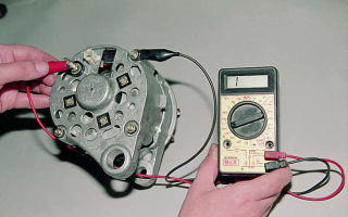
Measure the voltage between terminals “30” (“B+”) and the “ground” of the generator. The voltmeter should show the normal voltage for a given car (for example, for a VAZ “eight” and “nine” it is 13.5 - 14.6 V).
You can also check the regulated voltage by connecting a voltmeter directly to the battery terminals, but the results of such a test can be considered reliable if you are sure that the wiring is working properly.
In this case, the engine should operate at speeds close to maximum and you need to turn on the headlights and other consumers. The voltage value must match a certain value for a given vehicle.
To check the diode bridge , connect a multimeter or voltmeter to terminal “30” (“B+”) of the generator and to ground, in AC measurement mode. The AC voltage should not be more than 0.5 V. If the voltage is higher, then the diodes are faulty.
To check the breakdown to ground, you need to disconnect the battery and disconnect the wire going to terminal “30” (“B+”) from the generator. Next, you need to connect the device between the disconnected generator wire and terminal “30” (“B+”). If the device shows a discharge current of more than 0.5 mA, then a breakdown of the insulation of the generator windings or diodes is possible.
The strength of the output current of the generator can be checked using a special probe - this is an addition to the multimeter, in the form of pliers or a clamp, which is used to cover the wire, and thus measure the current flowing through the wire.
1. To measure the output current, cover the wire going to terminal “30” (“B+”) with the probe. Start the engine - it should be running at high speeds during measurement. Turn on the main electrical consumers one by one, and read the device readings separately for each consumer.
2. After this, you need to summarize these readings. Next, you need to turn on all consumers at the same time and take multimeter readings - this value should not be more than 5 A less than the sum of the readings when switching on the consumers one by one.
3. To check the excitation current of the generator, you need to start the engine and let it run at high speeds. Next, you need to place the measuring probe around the wire connected to terminal 67 (“D+”). The device will show the value of the excitation current - in a working generator it is 3-7 A.
To check the field windings, you will have to remove the voltage regulator and brush holder.
If necessary, clean the slip rings and make sure there are no breaks in the winding or a short to ground. To check, use an ohmmeter, applying its probes to the slip rings, and the resistance should be about 5-10 ohms.
Next, attach one probe of the device to any slip ring, and the other to the generator stator. The multimeter should show infinite resistance. If this is not the case, then the field winding is shorted to ground.
Here are the simplest measurement principles that can be performed using a multimeter:
Video: how to check the generator diode bridge.
Checking the generator with a multimeter - video:
How to properly check the generator on a car:
This article was written not only for car enthusiasts who prefer to repair cars with their own hands, but also, this information will be useful to all car owners to be in the know. Good luck!
(No one has rated it yet. Be the first!)
Loading…
Source: http://avto-i-avto.ru/diagnostika-neispravnostej/kak-proverit-generator-avtomobilya.html
No charging on VAZ 2106
views 19,003 Google+
Checking the generator connection diagram if there is no charging on the VAZ 2106
Checking the circuit when there is no charge on the VAZ 2106 is quite simple and the check takes about 10 - 15 minutes. Let me remind you that when checking the charge with an electronic voltage regulator, do not under any circumstances remove the terminals from the battery while the engine is running. Use a voltmeter or multimeter when checking.
The most common reason when there is no charging on a VAZ 2106 is the failure of the voltage regulator. To check, disconnect the terminals from the regulator and connect them to each other with the engine running.
If the circuit and generator are working properly, the voltage at the battery terminals will tend to the maximum and can reach 17V or more.
If the voltage begins to rise, then the circuit and generator are working, and the regulator needs to be replaced.
If the voltage does not begin to increase, then you should check the voltage on the wire that is connected to terminal 15 of the regulator with a test lamp or voltmeter.
If there is no power, check the power supply at the 9th fuse and the serviceability of the fuse. If normal, repair the break in the power supply wires of the fuse or from the fuse to the regulator.
Most often, the wire simply falls off the fuse block terminal.
If there is power on the wire of terminal 15, then test the integrity of the generator excitation circuit.
To do this, connect one end of the test lamp to the positive of the battery, and touch the other end, disconnected from the voltage regulator, to the wire that is connected to terminal 67 of the regulator.
If the control lamp is on, then the wire from the voltage regulator to the generator is working. The brushes and armature winding are also in good condition. The lack of charging in this case is caused by a malfunction of the rectifier (diode bridge) in the generator.
If the control lamp does not light up, then check the serviceability of the wire from the regulator to the generator by disconnecting it from the latter and connecting it to ground. The lighting of the control lamp indicates the serviceability of the wire and a possible malfunction of the brushes or armature winding. In this case, it is necessary to remove and repair the generator.
Alternator malfunction if there is no charging on the VAZ 2106
The reason when there is no charging on the VAZ 2106 is possible when the generator malfunctions, when the voltage drops when the load is turned on at medium engine speeds. This may be caused by a faulty alternator rectifier or a slipping drive belt. Determining this with a degree of probability is quite simple.
With normal drive belt tension, measure the voltage at the generator terminals at medium engine speeds without turning on consumers. The voltage should be between 13.5 - 14.5V. If the voltage gradually drops when the load is turned on, this indicates a malfunction of the rectifier.
If the voltage drops with a sharp increase in speed and can gradually increase to normal, then this indicates slipping of the drive belt. Critical wear of the drive belt is also indicated by the shine of the bottom of the generator pulley. In this case, even a tightened belt will slip and should be replaced.
If, when installing a new belt, it sinks significantly into the pulley groove, then the pulley is worn out and needs to be replaced.
Another reason for the voltage drop, and in some cases, the lack of battery charge, can be a violation of the contact between the wire connecting the negative terminal of the battery and the car body.
If the voltage at the battery terminals is higher than 14.5V, then you need to check the voltage at terminal 15 of the voltage regulator relay. If it differs by more than 0.5V, then it is necessary to find and eliminate the contact point in the circuit from the battery plus to the regulator.
The most common places are the ignition switch contact group and the fuse box. If the voltage at the relay is not low, then check the contact of the negative terminal of the relay, the metal plate under one of the relay mounting bolts, and the car body.
if there are no abnormalities in the contacts, change the voltage regulator.
“If you notice an error in the text, please highlight this place with the mouse and press CTRL+ENTER”admin 09/08/2014 “If the article was useful to you, share the link to it on social networks”
Source: https://avtolektron.ru/ramont-avtomobilya/net-zaryadki-na-vaz-2106
How to Check if the Generator Is Charging ~ AUTOREVIEWZ.RU
Why is the car battery not charged from the generator and how to deal with this?
The battery is considered the only source of voltage during the engine starting period. As you might guess, if it is not working, introducing the motor will undoubtedly be problematic. In this article we will tell you why a car generator interferes with charging the battery and what to do in such situations.
How to check the generator on a car. Basic malfunctions. Just something complicated
Detailed article on how to check the generator on a car WITHOUT REMOVING! We will use a multimeter and it will also be tested.
Charging process unavailable.
The diode indicator located on the control panel of the devices can indicate that the generator is interfering with charging the battery. Usually, this icon is depicted to replicate the appearance of the battery itself, and when the electronic part of a functioning engine is working well, it usually does not shine.
It is possible to see this indicator on the dashboard as soon as you turn the source in the lock to position I. At the same time, diagnostics of all devices is carried out, so the appearance of the indicator is absolutely normal.
In this case, if the indicator continues to glow while driving, this may indicate that the generator is not charging the battery.
In accordance with this, the driver needs to resolve this problem as soon as possible, because otherwise this can lead to more serious results than just an indicator appearing on the tidy.
From time to time, the generator unit does not charge the battery due to the latter being inoperable. At the same time, it will not be possible to solve this breakdown someday other than by replacing the battery.
Although from time to time this may be due to incorrect operation of the generator.
Prerequisites and methods of destruction of breakdown.
If you can temporarily seize a third-party battery for inspection, you can try installing it instead of your own in a car. Obviously, this battery must be fully functional. In fact, in this way you can find out what the root cause of the problem is in the battery or generator. Below we will look at the reasons for such a breakdown.
Internal condition of the battery.
Usually the reason why the generator is unable to determine the charge of the battery is the sulfation of the battery plates. In this case, the plane of the plates may be partially or completely covered with salts, which prevent the battery from charging.
In this case, if the level of plate coverage is small, then, in principle, it is almost always possible to try to restore the functionality of the battery. However, if the destruction process is already irreversible, it will undoubtedly be necessary to replace the device.
Regarding the restoration of the battery system from sulfation, this process can take a long time (borrow) for more than one day, but the result and quality of restoration cannot be ensured.
From this we can conclude that, in one way or another, over time you may need a fresh battery. The resuscitation procedure usually begins during this time, when the battery shows no symptoms of swelling, mechanical damage, cracks, etc.
In other words, the device body must be intact.
Installing battery terminals to terminals.
Although it follows in the footsteps, it should be taken into account that the external condition is sometimes far from a guarantee of what the outcome will do for you. Inside the system there are banks in which the plates have a good chance of breaking off, which ultimately leads to the appearance of a short circuit. If this is the case, for example, then there is no other choice other than buying a fresh battery.
Terminals.
From time to time, the appearance of an indicator light may occur while driving a car. At the same time, there is no need to give in to vanity, because the root cause may be quite obvious.
If you hit a bump or a hole, the contact may simply fly off the battery, this can especially happen if the terminal was not screwed in well.
If this is the case, then you just need to return it to the space and tighten it more.
Problems with the terminals have a good chance of manifesting themselves if they become oxidized in the space where they are connected to the terminal. To solve this problem, the oxidation must be simply cleaned up. To achieve the desired result you will need a small grit sandpaper.
During the process, you must be very careful, because it is possible to accidentally cut off the lead portion of the output, and this is unacceptable.
If you erase more layers than necessary, the terminal will undoubtedly not adhere well and will begin to fall5 on any bump (video creator Avramenko Garage).
Generator belt.
What charge must the generator supply and for what reasons does the battery overcharge or impossibility of charging occur? Often the problem is hidden in the knot's strap; when the tension is weak, the belt will begin to slip on the shaft, at which point the knot cannot provide force to the system. The battery is switched and the charged battery is converted from an energy buyer into a consumption key, which is evenly discharged.
Diagnostics of the degree of belt tension can be carried out with the engine turned off. If the internal combustion engine is turned off, you can try to tighten it as necessary. Although it is important to take into account that slippage can be caused not only by poor tension, but also by wear of the profile. This problem can be solved only by replacing the strap.
The impossibility of transmitting rotation can result from a wet or wet shaft; the strap will undoubtedly slide along the plane without effort. In order for the battery to be able to charge well, the pulley must be dry, so it will certainly only need to be dried. Finding slippage is quite difficult; in this case, it is possible for the strap to twist.
The root cause of the difficulty may lie in the oxidation of the wires on the generator unit in the connection spaces.
If you see a snow-white attack, then, as stated above, it can be removed using sandpaper. Conduct a visual inspection for the possible presence of broken wires or burnt contacts.
If the wire is burnt out, it is possible to indicate the corresponding scent (creator of the video VAZ 2101-2107 REPAIR AND SERVICE).
Monitoring other components of the charging system.
Source: http://autoreviewz.ru/kak-proverit-daet-li-zarjadku-generator/
How to check the charging of the generator? – Automotoguru
05.04.2014
|
215231
|
DIY repair
|
The main source of power in a car is a generator; it is like a “mini-power station”. Incorrect or unstable operation of this unit can result in poor battery charging.
A failed generator does not provide charging, therefore, the on-board network of the car will work on a battery that will not last long.
As a result, the battery is completely discharged, the engine “stalls” somewhere outside the city, and you have a new “headache” and the need to replace the generator.
In order to prevent such a scenario, it is necessary to regularly monitor the condition of this device, as well as the charging it provides. If you notice any interruptions in operation, you need to check the generator, and you will now learn how to do this.
But before that, I think it is necessary to talk about precautions and certain rules that must be followed when checking this electrical appliance in order not to damage it.
!!! It is forbidden:
- Check the functionality of the generator by short circuiting, that is, “to spark.”
- Connect terminal “30” (in some cases “B+”) with “ground” or terminal 67 (in some cases “D+”).
- Allow the generator to operate without consumers turned on; operation with the battery disconnected is especially undesirable.
- Perform welding work on a car body with the generator and battery wires connected.
- !!! Important:
- The test is carried out using a voltmeter or ammeter.
- The valves are checked with a voltage not exceeding 12 V.
- When replacing the wiring of an electric generator, it is necessary to select wires of a similar cross-section and length.
- Before checking the device, make sure that all connections are working and that the drive belt is properly tensioned. A belt is considered to be correctly tensioned if, when pressed in the middle with a force of 10 kgf, it bends no more than 10-15 mm.
How to test a generator with a multimeter or voltmeter?
Checking the voltage regulator
- In order to check the voltage regulator, you will need a voltmeter with a scale from 0 to 15 V. Before starting the test, you should warm up the engine for 15 minutes at medium speed with the headlights on.
- Measure the voltage between the generator ground terminals and “30” (“B+”).
The voltmeter should show normal voltage for a particular vehicle. For example, for a VAZ 2108 it will correspond to 13.5 – 14.6 V. If the voltage is lower or higher, the regulator most likely requires replacement.
- In addition, you can check the regulated voltage by connecting a voltmeter to the battery terminals. It should be noted that the result of such a measurement will not be accurate if you are sure that the wiring is 100% intact.
In this case, the engine should operate at medium speeds with the headlights and other consumers of electricity turned on. The voltage size must match a certain value for a specific car model.
Checking the generator diode bridge
- Turn the voltmeter into AC measurement mode and connect it to ground and terminal “30” (“B+”). The voltage should be no more than 0.5 V, otherwise there is a possibility of diode failure.
- To check the breakdown for ground, you need to disconnect the battery and also remove the generator wire that goes to terminal “30” (“B+”).
- Then connect the device between terminal “30” (“B+”) and the disconnected generator wire.
If the discharge current on the device exceeds -0.5 mA, it can be assumed that there is a breakdown of the diodes or the insulation of the generator diode windings.
- The strength of the recoil current is checked using a special probe, which is an addition to the multimeter.
It is something like a clamp or pliers that grips the wires, thus measuring the strength of the current that passes through the wire.
Checking the return current
- To measure the recoil current, you need to cover the wire that goes to terminal “30” (“B+”) with a probe.
- Then, start the engine and take a measurement; during the measurement, the engine should be running at high speeds. Turn on electrical appliances one at a time and take measurements for each consumer separately.
- Then calculate the readings.
- The following test must be carried out with all energy consumers switched on at the same time. The measurement value should not be lower than the sum of the readings of each consumer, when you measured each of them in turn, a discrepancy of 5 A downward is allowed.
Checking the generator excitation current
- To check the generator excitation current, start the engine and give it high speed.
- Place the measuring probe around the wire connected to terminal 67 (“D+”), the readings on the device will correspond to the value of the excitation current; on a working electric generator it will be 3-7 A.
To check the field windings you will need to remove the brush holder and voltage regulator. It may be necessary to clean the slip rings, and also check for breaks in the windings or short circuits to ground.
- For this test, an ohmmeter is used, its probes must be applied to the slip rings, the resistance value should be in the range of 5-10 Ohms.
- Then connect one ohmmeter probe to any slip ring, the second probe to the stator. On a working generator, the multimeter will show an infinitely high resistance, otherwise the field winding will short to ground.
Video on how to check a car generator with your own hands:
Current:
- How to check the ignition coil yourself
- Self-replacement of the ignition switch of a VAZ 2110
- How to check the air flow sensor of a VAZ 2110? Replacing the VAZ mass air flow sensor with your own hands
Driver's manual
We will be grateful if you share this article on social media. networks
Checking the generator with a multimeter
You can check it yourself with a regular tester turned on in ohmmeter mode (resistance measurement). First we check the rotor, then the stator and then the diode bridge. Let me remind you that the generator also has a brush assembly and a voltage regulator.
Sometimes these two nodes are structurally combined into one node. In general, start your checks by visually inspecting the brush assembly. After all, if the brushes do not reach the slip rings, then the unit will not produce electricity.
The easiest way to check the charging system
Measure the battery voltage with the engine not running , if the battery is not discharged, then the voltage should be 12.5 - 12.8 volts.
Now you need to start the engine and measure the voltage on the battery. Permissible voltage limits are 13.5-14.5. The permissible maximum charging on some vehicles is 14.7 volts.
Please note that if the battery is discharged, the voltage at its terminals when the engine is running may be higher.
Simple check on the car
Without removing it from the car, you can carry out a number of simple preliminary checks.
Checking the alternator on a car also allows the use of a tester or multimeter. When the engine is running, turn on the maximum number of power consumers and check the voltage on the battery. It should not fall below 12.8 volts.
Rotor check
Using a multimeter in resistance measurement mode, ring the excitation winding (on the rotor).
To do this, attach the measuring probes to the slip rings.
The resistance of a serviceable winding should not be in the range of 2.3 -5.1 Ohms.
- If there is no resistance at all, then there is a break in the winding.
- If the resistance is lower than expected, then there is most likely an interturn short circuit.
- If it is higher, then there may be poor contact or the winding leads to the slip rings are not properly soldered.
We also measure the current consumed by the excitation winding. To do this, we apply +12 volts to the slip rings and connect a DC ammeter to the open circuit.
The current consumed by the winding should be within 3-4.5 Amperes. If the current is too high, it means there is interturn ignition in the rotor winding and it requires replacement.
The maximum current of the relay regulator is 5 Amps, so if the rotor winding current is too high, the voltage regulator also needs to be replaced.
Insulation resistance can be checked with a high alternating voltage of 220 volts by applying voltage through a 220 V, 40 W incandescent lamp.
, we connect one contact to the slip ring, the other to the metal rotor housing. If there are no short circuits to the housing, the lamp should not light.
If the lamp filament glows even just a little, then there is a current leak to ground. This winding requires repair or replacement.
Take precautions when working with high voltage!
Generator stator
The stator windings can only be examined by disconnecting or unsoldering the leads from the diode bridge. The resistance between the terminals of the windings should be approximately 0.2 Ohm. And between the terminal of any winding and 0 (common terminal) there is about 0.3 Ohm. If the stator windings or diode bridge are shorted, the generator makes a loud noise during operation.
Also carefully inspect the condition of the internal parts of the stator and the outer part of the rotor. They should not touch each other during operation. As they say, “shoes.” During such operation, the generator makes increased noise, which indicates wear of the bearings or bushings.
Video, testing on a homemade stand:
Diode bridge
A diode bridge consists of two plates, one of which is positive and the other negative. Diodes are checked with a multimeter in ohmmeter mode.
Connect one probe to the “+” terminal of the diode bridge, and alternately connect the second to terminals F1 F2 F3 and 0. To make it clearer: we connect one probe to the positive plate, and with the other we alternately touch the terminals of those diodes that are pressed into this plate.
Then swap the probes and do the same. In one case the tester should show conductivity (some kind of resistance), but in the other it should not. So we checked the diodes on the positive plate.
To check the diodes on the negative plate, connect one probe to the negative plate, and the second to the leads of the diodes alternately. In exactly the same way, then we swap the probes and repeat the procedure. In one case there will be conductivity, in the other there will not be.
Brushes and slip rings
Rings and brushes can be checked visually, assessing their condition and serviceability. Check the protruding length of the brushes. It must be at least 4.5 mm. And the norm is 8-10 mm.
Also, the diameter of the slip rings must be at least 12.8 mm. and ideally 14.2-14.4. Worn rings can be replaced if you find them in a store. They are removed with a special puller, and the winding terminals are unsoldered. After installing new rings, they can be turned on a lathe to eliminate runout and sanded with fine sandpaper to eliminate burrs.
Engine lubrication system design.
Source: https://avtomotoguru.ru/kak-proverit-zaryadku-generatora/
How to test a generator with a multimeter
What to do if there is no light in the house? A current generator can help solve the problem. But if this equipment also fails, checking the generator with a multimeter will help determine the malfunction. Regardless of the type and brand, with the help of this device, once you find out the cause of the malfunction, you can carry out simple repairs yourself.
There are many types of generators, from large and powerful industrial devices to small automotive devices. But the testing algorithm using the tester is the same for any generator.
What components and parts are checked using a multimeter?
This operation involves diagnosing the electrical part, and checking the following parts:
- Voltage measurements are taken at the generator output;
- the rotor excitation winding is checked for open circuit or short circuit to the housing;
- checking the stator windings for breakdown and open circuit;
- carry out fault detection of the diode bridge, capacitor;
- faults in the voltage regulator and brushes are detected;
Performing each of the listed operations requires special knowledge and skill to carry out measurements, so each test should be considered in more detail.
Output voltage level measurement
For each individual unit this value will be different. Let's take a closer look at checking a car generator. Set the voltage measurement mode on the multimeter scale. First you need to check the voltage with the engine turned off. To do this, measure the voltage value at the battery terminals.
We connect the red probe to the positive terminal, and attach the black one to the minus terminal. A charged, serviceable battery will produce a value of up to 12.8 V. We start the engine. Then we take a measurement. Now this value should be no more than 14.8 V, but no less than 13.5 V. If the voltage level is higher or lower, the generator is faulty.
Checking the rotor winding
To perform this operation, it is necessary to dismantle and disassemble the unit. When performing a self-test, do not forget to set the device to the circuit resistance measurement mode. Additionally, a value of no higher than 200 Ohm is set. These routine maintenance works are carried out in 2 stages:
- Measuring the resistance value of the rotor windings. To do this, we attach the probes to the rings of the moving part of the engine and determine the value. This will make it possible to determine the probability of a winding circuit break at a value above 5 ohms. If the device shows less than 1.9 ohms, a turn short circuit has occurred. Most often, the chain breaks at the junction of the rotor winding lead to the ring. You can determine the defect by moving the wire with a probe at the soldering points, as well as by detecting darkened and crumbling wire insulation. In the event of a break or short circuit (short circuit), the wires become very hot, so the breakdown can be detected by visual inspection.
- A circuit test is performed to detect a short circuit to the frame. We position the generator rotor conveniently for operation. Then we bring one probe to the rotor shaft, and attach the second to any ring. If the winding is working properly, the resistance reading will go off scale. If it shows low resistance, this part should be sent for rewinding. When rewinding the rotor, it is important to maintain perfect balancing.
Checking the stator windings
Checking the stator begins with a visual inspection. We pay attention to external damage to the housing and insulation, and places where wires are burned during a short circuit.
The faulty unit should be rewound or replaced. If the external integrity of the wires is established, we begin to investigate using a tester.
When performing work to check the normal state of the node, we make sure:
- The integrity of the winding circuit. To do this, set the device to resistance measurement mode. We attach the probes to the first pair of terminals, then check the 1st winding and the 3rd, 3rd and 2nd terminals. If, during a break, the pointer of an analog device goes off the scale, the windings should be rewinded.
- In the absence of an interturn short circuit and to the housing. To do this, connect one of the tips to the terminal, the second to the body. If the windings are short-circuited, the scale will have a lower resistance value than those in good condition.
Voltage Regulator Troubleshooting
Remove and disconnect the wires from the part. We inspect the condition of the brushes. They should not have significant defects or chips. In the guide channels of the brush holder, the generator brushes must move freely. If they protrude beyond the edge by less than 5 mm, the generator regulator should be changed.
The test is carried out using batteries and a 12-volt light bulb. The voltage of the second power source must be at least 15 V, so we connect the batteries in series to the car battery and adjust the value to the desired value. We attach the plus from the 1st power source to the output contact, and the minus to ground.
The light bulb is installed between the brushes. When connecting a 16 V source, it should not light up. With a weaker battery, it lights up. If proper combustion is not observed, the regulator should be replaced.
Checking the diode bridge and capacitor
The purpose of this unit is to prevent the passage of electricity to the generator. It must direct it from the generator to the consumer. In this case, any deviation is a malfunction of the diode bridge. To check, we dismantle it and solder the terminals on the generator. We set the device to “ring”.
To check the power diode, we bring the black probe to the bridge plate, and attach the red probe to the output. If the multimeter reading is 400-800 Ohm, the diode is working, other numbers require replacing the diode or bridge.
When checking the auxiliary diode, the operation is performed in a similar way. But when the probes are swapped, the device should show a resistance value tending to infinity.
When checking a polar capacitor, you need to remove the remaining charge. Then, set the resistance measurement on the scale. The contacts must be attached with correct polarity. When measuring a working part, the resistance gradually increases. Otherwise, when the screen shows 0, it should be replaced.
If a non-polar capacitor is being tested, the value scale is set to MOhm. We place the probes on the contacts regardless of polarity. Then, you need to measure the resistance value. If the number on the screen is less than 2 ohms, this is a faulty part.
In conclusion, it is necessary to recall that all measurements when checking the functionality of the generator using a multimeter are carried out by measuring the value of the electric current resistance.
Only to measure the voltage at the output of the generator, the device is configured to measure this value. Any beginner can test a generator with a multimeter.
You just need to work with full responsibility and follow the instructions.
Source: https://EvoSnab.ru/instrument/test/proverka-generatora-multimetrom
How to test a generator with a multimeter
The malfunction of the car generator is classified as critical, in which further operation of the vehicle is not allowed. You can use a multimeter to check the functionality of the generator.
Signs of generator failure
Signs of abnormal operation of a car generator may include:
- no “battery” indication on the dashboard when the ignition is turned on;
- the “battery” light glows after starting the engine;
- periodic blinking of the “battery” signal indicator while driving;
- the smell of burnt electrical wiring in the generator area;
- failure to start the engine after parking.
Lack of battery charge with a faulty generator leads to problems with starting the engine. More dangerous is a malfunction associated with exceeding the current and voltage of the car battery charge.
Many car enthusiasts use a donor battery to start the engine, after which they disconnect the battery terminals to switch to charging their own battery.
At this moment, the vehicle's electrical equipment is powered by a generator.
If the generator is faulty, the voltage in the on-board network may be more than 17 volts, which leads to breakdown of the protective zener diodes in the engine control unit. In this case, expensive repairs to the engine control unit are required.
Causes and possible consequences of the malfunction
The generator may not work for the following reasons:
- malfunction of the voltage regulator (“pills”, “chocolates” in the slang of car enthusiasts);
- wear (destruction) of brushes;
- short circuit of the exciting winding (rotor);
- breakdown of diodes (located in the horseshoe);
- wear of bearings and bushings.
A faulty voltage regulator usually results in a lack of battery charge. In this case, the “battery” indicator light appears on the dashboard. The engine continues to run until the battery is discharged to approximately 8 - 9 volts.
During daylight hours, the battery charge may be enough for 30-50 kilometers, provided that the battery was well charged at the time the malfunction occurred.
If the output stages of the voltage regulator breakdown, a malfunction may occur due to an increase in the generator output voltage to 17 - 20 Volts. This recharges the battery. The consequence of overcharging is the process of boiling of the electrolyte. If signs of corrosion appear under the hood in the battery area, it is necessary to check the generator.
A breakdown of the diode bridge can occur when the battery is accidentally reversed (installing the terminals in the wrong polarity). Typically, diodes are punched in pairs in one arm. A faulty diode has a resistance close to zero. In this case, the stator winding of the generator operates in short circuit mode and becomes very hot.
After a few minutes of engine operation, the windings overheat, and a smell of burnt electrical wiring appears under the hood of the car. To avoid fire, the engine must be turned off and the generator checked.
Wear of the brushes leads to gradual failure of the generator. First, while driving, the charge indicator light on the dashboard begins to blink, then it begins to glow constantly. In many generator models, the brushes are changed together with the voltage regulator.
A short circuit in the generator windings can lead to a significant change in output parameters and overheating of the device.
Initial check sequence
An initial performance check can be performed without dismantling the generator. To do this, set the multimeter switch to the “constant voltage 20V” mode.
Next, connect the black probe to the negative terminal of the battery, the red one to the positive terminal. After this, you need to start the engine and let it reach a stable idle speed.
Multimeter readings ranging from 13.5 to 14.5 Volts are considered normal.
If the multimeter shows a value less than 12.8 Volts, the charging process either does not occur at all, or the charging current is extremely small. The generator is operating in abnormal mode. When the voltage is more than 14.8 Volts, the battery is overcharged. This can lead to boiling of the electrolyte, an increase in acid concentration, and destruction of the battery plates.
To check the voltage at the generator output, you need to turn on the car lamp in the open circuit from terminal 30 on the generator (the point of contact with the thick wire leading to the positive terminal of the battery or starter).
Next, connect the multimeter in the “=20V” mode with the red probe to contact 30 of the generator, and the black probe to the stripped contact on the engine or body. Start the engine. The reading on the multimeter should not be more than 15.5 volts whenever the accelerator pedal is pressed. Otherwise, further operation of the generator is dangerous for the electrical equipment of the car.
When checking, you should evaluate the degree of tension of the generator belt. Using a simplified method, this can be done by pressing on the belt with your finger.
The amount of deflection should be within 0.5 - 1 centimeter.
At the same time, check the degree of belt wear. To determine the reasons for abnormal operation of the generator and perform repair work, dismantling the generator is required.
Checking generator components
The test begins with monitoring the functionality of the voltage regulator. To do this, the regulator is removed from the generator and a simple electrical circuit is created.
Any car interior light bulb can be used as an incandescent lamp. If voltage regulator 3 is working properly, lamp 6 should not glow at full power.
When connected in parallel with the lamp (brushes) of a multimeter, its readings should be from 5.0 to 10.0 Volts. If the multimeter readings fall outside these limits, the regulator must be changed.
The design of some generator models allows for the possibility of replacing the regulator without dismantling the device.
Next, check the exciting winding of the generator for breakdown. To do this, set the multimeter to resistance measurement mode at a limit of 200 kiloOhms. The probes are connected: black - to the commutator lamella, red - to the metal part of the armature. The resistance should be more than 100 kiloohms or higher than the upper limit of measurement, as shown in the photo.
The resistance between the lamellas (rotor windings) is usually 0.5 - 2 Ohms.
Checking the stator begins with checking the windings for breakdown. To do this, the red probe of the multimeter is connected to the metal part of the stator, the black probe is connected in series to the windings.
The resistance must be above the upper measurement limit. Then the resistance between the winding contacts is measured. They should differ by no more than 5%. The measurement limit of the multimeter is set to 200 ohms.
If the winding has an electrical breakdown, a short circuit of the turns or a break, it must be replaced. There are workshops that rewind stators and rotors.
To check the health of the diode bridge, the multimeter measurement mode is switched to the “diode” test. Then the diodes (their number on a horseshoe is usually 9) are sequentially “ringed” in forward and reverse connection. In the forward direction (black probe to the cathode) the resistance is 550 - 700 Ohms, when switched in reverse it is greater than the maximum measurement limit.
When the diodes breakdown, the resistance in all directions will be practically zero. This diode should be changed. The difficulty of replacing a diode lies in the fact that the diodes in generators are not soldered, but spot welded to ensure reliable contact at different temperature conditions.
A car generator is an important part of a car's electrical equipment. At the first sign of inoperability, it is necessary to check it using a multimeter.
Source: https://instrumentiks.ru/sovety/kak-proverit-generator-multimetrom