Checking and adjusting the clearances in the valve drive 1NZ-FE and 2NZ-FE – Tech Doc Toyota
Note :
checking and adjusting the clearances in the valve drive is carried out on a cold engine.
1. Remove the cylinder head cover (see section “Timing Chain”).
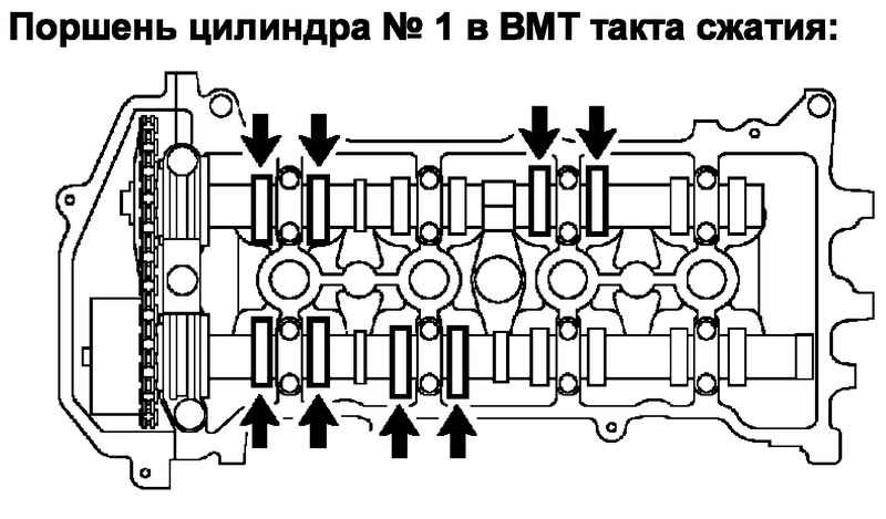
2. Set the piston of the first cylinder to TDC on the compression stroke.
a) Turn the crankshaft pulley and align it with the “O” mark on the timing chain cover.
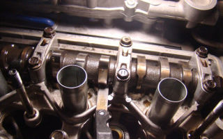
b) Make sure that the timing marks on the camshaft sprocket and VVT sprocket are facing up as shown in the illustration.
If the marks are not pointing upward, rotate the crankshaft one turn and align the marks again.
3. Measure the clearance in the valve drive marked in the figure.
a) Using a feeler gauge, measure the gap between the pusher and the back of the camshaft cam.
b) Write down the values of the gap outside the specified limits. These values will be used later to select the required pusher size.
Nominal valve clearance (cold engine):
intake …………………. 0.15 - 0.25 mm
graduation ………………. 0.25 - 0.35 mm
c) Turn the crankshaft one revolution (360°) and align the marks.
d) Check the valve drive clearances shown in the figure by repeating the procedure in point (a).
4. If necessary, adjust the clearances in the valve drive.
a) Set the piston of the first cylinder to TDC on the compression stroke.
b) Mark the timing chain and camshaft sprocket.
c) Remove the two plugs from the cylinder head cover.
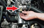
d) Using a screwdriver, while rotating the exhaust camshaft slightly to the right, rotate the tensioner lock plate down and press the tensioner plunger as shown in the figure.
Note : if the locking plastic is difficult to lower, repeat the operation, slightly turning the exhaust camshaft left and right.
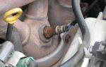
e) Install a rod with a diameter of 2-3 mm through the hole into the locking plate and tensioner, thereby fixing the locking plate.
Note:
— To make it easier to fix the rod, turn the camshaft slightly left and right.
— Secure the rod with electrical tape so that it does not fall out.
e) Remove the timing chain from the sprocket.
Note:
— Do not rotate the crankshaft with the timing chain removed.
— If it is necessary to rotate the camshaft with the chain removed, before rotating, turn the crankshaft counterclockwise 40° from TDC and align the oil nozzle hole with the mark.
— If the chain is difficult to remove, slightly turn the intake camshaft left and right.
g) Fix the hexagonal part of the camshaft with a wrench, remove the bolt and remove the VVT sprocket with chain.
Attention :
do not disassemble the VVT system sprocket assembly!
h) Remove the intake and exhaust camshafts.
Note :
When removing the chain from the VVT sprocket, secure the chain.
i) Secure the chain with a cord as shown in the figure.
Note:
— Be careful not to drop anything into the internal cavity of the timing chain cover.
— Do not allow the chain to come into contact with water or dirt.
j) Remove the valve tappets.
k) Determine the size (thickness) of the new pusher.
— Using a micrometer, determine the thickness of the pusher being replaced.
— Calculate the thickness of the new pusher using the formula so that the clearance in the valve drive is within the recommended range,
For intake valves ………. N = T + ( A - 0.20) mm
For exhaust valves ……………. N=T + ( A - 0.30) mm, where:
N
is the thickness of the new pusher,
T
is the thickness of the removed (used) pusher,
A
is the measured gap in this valve.
Nominal valve clearance (cold engine):
intake …………………. 0.15 - 0.25 mm
graduation ………………. 0.25 - 0.35 mm
Note :
pushers are available in 35 sizes in 0.02 mm increments, with thicknesses ranging from 5.06 mm to 5.74 mm.
m) Install the valve lifters (see the “Engine - General Repair Procedures” section).
i) Turn the crankshaft pulley and align it with the “O” mark on the timing chain cover.
o) While holding the chain, install the intake camshaft and sprocket assembly,
p) Align the marks on the chain and the camshaft sprocket, p) Install the two camshafts and sprockets assemblies (see the “Cylinder Head” section).
c) Remove the rod from the timing chain tensioner.
r) Make sure the timing marks on the sprockets are facing up as shown in the illustration.
y) Make sure that the timing marks and chain marks are aligned as shown in the illustration.
f) Install two new plugs into the cylinder head cover.
Torque. ………………….. 15 Nm
x) Check the clearance in the valve drive (see above).
5. Install the cylinder head cover
cylinders (see section “Cylinder head”).
tech doc corolla 2000-06
Source: http://avto-remont-toyota.ru/proverka-i-regulirovka-zazorov-v-privode-klapanov.html
Adjusting valves Toyota Corolla 2007-2010
Any machine after a long period of operation requires tuning, adjustment or repair. Regardless of whether it is a foreign or domestic car. We know that in our country there are practically no good roads or quality fuel. Therefore, car adjustments, tuning or repairs happen more often than we would like.
Here I want to tell you how the 2007-2010 Toyota Corolla valves are adjusted , disassembled and reassembled. Why are valves knocking? Gaps increase and parts wear out. In 1ZZ engines, hydraulic compensators that automatically adjust valve clearances due to oil pressure are not provided.
Instead, there are adjusting pushers of different thicknesses, the cups of which perform two functions: the pusher function and the washer function. For a more revving engine this would be normal, but for the 1ZZ engine, valve adjustment with such a system became much more complicated. One good thing is that the valves are not adjusted so often.
Once every 80 thousand km.
Valve knocking usually occurs every time the engine is started in cold weather. As it warms up, the knocking noise subsides and soon disappears completely. That is, the metal warmed up, the gaps decreased, and accordingly the knocking disappeared.
And the more the car is used with what may seem to some to be an insignificant problem, the faster not only the tuning and adjustment of the Toyota Corolla 2007-2010 valves will creep up, but also serious repairs. Spare parts for this motor are not that cheap.
In particular, assembled pushers of various sizes are very difficult to find, and there are not many craftsmen who can correctly adjust the gaps.
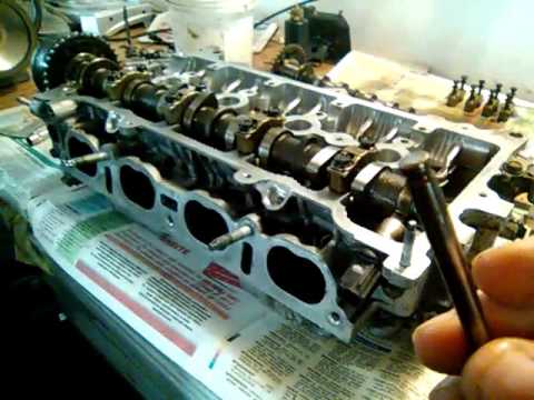
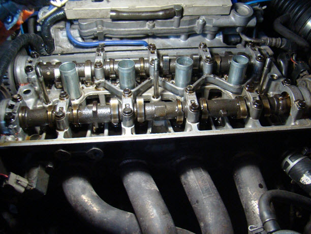
And so, remove the valve cover and put it aside. Before us is the timing mechanism. Set the piston of the first cylinder to the top dead center of the compression stroke.
Using a flat feeler gauge, measure the gaps between the camshaft cams and the pushers of the intake valves of cylinders 1 and 3 and the exhaust valves of cylinders 1 and 2.
The clearances on a cold engine for intake valves should be 0.15-0.25 mm, for exhaust valves 0.25-0.35 mm. Measurement data that does not match the factory settings should be recorded. They will be needed later when valve lifters are selected.
Next, we crank the crankshaft one cycle and set the piston of cylinder 4 to the top dead center of the compression stroke. We check the intake valves of cylinders 2 and 4, and the exhaust valves of cylinders 3 and 4. We measure the gaps with the same flat feeler gauge and write down the changed data in our notebook so that further adjustment of the 2007-2010 Toyota Corolla valves will be successful.
The next step is to remove the camshaft. The valve tappets are released. We take measurements using a micrometer. Next, we compare the data on the dimensions of the removed valve tappets with the dimensions specified in the vehicle specifications. Naturally, you will see the difference, otherwise your engine would not knock, and you would not be adjusting the valves.
Here's a small example of how to calculate excess clearance: intake valves - measured clearance is 0.4 mm.
0.4 mm – 0.2 mm = 0.2 mm (measured gap – nominal gap = excessive gap)
Valve pusher: measurements showed that the thickness of our pusher is 5.25 mm.
0.2 mm + 5.25 mm = 5.45 mm
Excessive clearance + working tappet thickness = new original tappet thickness. This means that the most optimal thickness of the pusher will be 5.46 mm. We select the pusher from No. 46.
And so, we now know that adjusting the valves of Toyota Corolla 2007-2010, although not an easy task, is quite solvable. And if you have the necessary tools and spare parts, you can perform this entire procedure yourself.
Reassembling the car, after adjusting and adjusting the valves, is done in the reverse order.
Sergey Demin specially for the Avtoliteratura website
Source: http://myautobook.ru/publ/toyota_remont/toyota_corolla_2007_2010g/regulirovka_klapanov_toyota_corolla_2007_2010/8-1-0-29
Adjusting thermal clearances in valves of Toyota 4A-FE, 5A-FE, 7A-FE engines
____________________________________________________________________________
____________________________________________________________________________
Adjusting the thermal clearances of Toyota engine valves 4A-FE, 5A-FE, 7A-FE
Toyota 4A-FE engines of Toyota Carina E, Toyota Corolla, Toyota Crown (AE92, AE95, AT171 and AT180) – Disconnect the high-voltage wires from the spark plugs, holding them only by the rubber tips. Improper handling of wires may result in internal wire breaks.
– Remove the protective cover for the engine electrical wiring and disconnect the electrical wiring from the cylinder head cover. – Disconnect the positive crankcase ventilation system hoses from the crankcase ventilation valve. – Unscrew the 3 cap nuts, remove the rubber bushings and the cylinder head cover along with the gasket.
Engines Toyota 4A-FE (AE101, AT190), 5A-FE and 7A-FE for Toyota Carina E, Toyota Corolla, Toyota Crown, Carib, Sprinter
– Disconnect the high-voltage wires from the spark plugs, holding them only by the rubber tips. Improper handling of wires may result in internal wire breaks. – Disconnect the generator connector, generator wire, emergency oil pressure sensor connector, two electrical wiring clamps. – After unscrewing the two bolts, remove the protective cover for the engine electrical wiring and disconnect the electrical wiring from the cylinder head cover. – Disconnect the 2 positive crankcase ventilation hoses from the cylinder head cover. – Unscrew the 4 cap nuts and remove the sealing washers, cover and cover gasket.
Toyota 4A-FE engines for Toyota Carina E, Toyota Corolla, Toyota Crown (AE92, AE95, AT171 and AT180)
Make sure that the valve lifters of the 1st cylinder are free, and the valve lifters of the 4th cylinder are tightened.
If this condition is not met, then turn the crankshaft clockwise 1 revolution (3600) and again align the groove on the pulley with the corresponding mark.
Engines 4A-FE (AE101 and AT190), 5A-FE and 7A-FE for Toyota Carina E, Toyota Corolla, Toyota Corona, Carib, Sprinter
Make sure that the hole on the camshaft drive pulley aligns with the mark on the bearing cap. – Using a feeler gauge, measure the gap between the valve tappet and the back of the camshaft cam.
– write down the values of the gap that goes beyond the limits specified in the technical specifications; these values will be used to select the required shim size.
Nominal thermal clearance in valves (on a cold engine).
Intake:
ICE 4A-FE, 5A-FE and 7A-FE – 0.15-0.25 mm
Graduation:
internal combustion engine 4A-FE (AE101 and AT190) – 0.20-0.30 mm 5A-FE and 7A-FE – 0.25-0.35 mm internal combustion engine 4A-FE (AE92, AE95, AT171 and AT180) – 0.20 -0.30mm Turn the crankshaft 1 revolution (3600) and again align the groove on the pulley with the corresponding mark and check the valve clearances.
ICE 4A-FE (AE92, AE95, AT171 and AT180) Adjust the thermal clearance in the valves. Replace the adjusting washer: – Rotate the crankshaft so that the protrusion of the valve cam, in which the clearance is adjusted, is oriented upward and does not touch the tappet.
– Using a suitable tool, press the valve tappet and place the tool between the camshaft and the valve tappet; then remove the device. – Remove the shim using a small screwdriver and a magnet.
– Determine the size (thickness) of the shim that provides the clearance in accordance with the specifications and select the shim.
– Install a new shim, place the washer on the valve tappet, use the tool to press the tappet and remove the tool – Recheck the clearance.
Toyota engines 4A-FE (AE101 and AT190), 5A-FE and 7A-FE for Toyota Corolla, Corona, Toyota Carina E, Toyota Sprinter, Caldina
Adjust the thermal clearance in the valves – In these engines, to adjust the thermal clearance in the valves, the camshafts must be removed.
– Since the axial clearance of the camshaft is very small, when dismantling the shaft it must be held in a horizontal position, otherwise the seat of the camshaft thrust washer in the cylinder head may be damaged, which may cause the camshaft to seize or break.
Similar requirements must be observed when installing camshafts. – The methods for adjusting the clearance of the intake and exhaust valves are slightly different from each other. Adjust the thermal clearances in the intake valves. Remove the intake camshaft.
– Turn the crankshaft pulley of the Toyota 4A-FE (AE101 and AT190), 5A-FE and 7A-FE internal combustion engines so that the hole in the auxiliary gear (through which the auxiliary gear is mounted on the camshaft drive gear) is at the top; this allows the cams of cylinders 1 and 3 to apply equal pressure on the corresponding valve tappets.
– Unscrew the 2 bolts and remove the cover of the 1st camshaft bearing. – Attach the camshaft slave gear to the drive gear using a set bolt. – Evenly loosen and remove the 8 camshaft bearing cap bolts in several passes; then remove the bearing caps and camshaft.
Remove the shim using a small screwdriver. Determine the size (thickness) of the shim that will provide clearance to specifications. – Using a micrometer, measure the thickness of the removed shim. – Determine the thickness of the new shim that will provide the required thermal clearance in the valves.
Select the shim whose thickness comes closest to the value. The adjusting washers have 16 sizes (thickness values) from 2.55 mm to 3.30 mm in 0.05 mm increments. Install a new shim onto the valve tappet. Install the intake camshaft of the Toyota internal combustion engine 4A-FE (AE101 and AT190), 5A-FE and 7A-FE.
– Rotate the crankshaft pulley and position the exhaust camshaft so that its dowel pin is higher than the cut of the cylinder head. – Apply grease to the non-thrust surfaces of the camshaft.
– Connect the intake camshaft gear to the exhaust camshaft gear, aligning the timing marks of both gears. It is necessary to distinguish the timing marks from the TDC marks and not use the latter in this case. – After this, place the camshaft in the bearing bed, maintaining the mesh of the gears.
This position of the camshaft allows the cams of the first and third cylinders to evenly press the pushers of the corresponding valves. – Reinstall the four camshaft bearing caps. – Apply a thin layer of engine oil to the threads and under the heads of the camshaft bearing cap bolts.
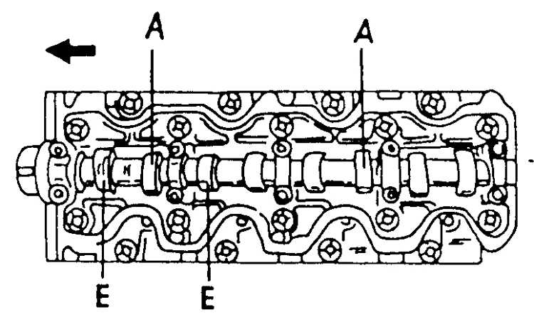
– Install and evenly tighten the 8 bearing cap bolts in several passes in the sequence shown. – Remove the installation bolt. – Install the 1st bearing cover with the “arrow” mark facing forward. If the 1st bearing cap does not fit into place, use a screwdriver to move the camshaft back.
– Apply a thin layer of engine oil to the threads and under the camshaft bearing cap bolt heads. – Install and tighten the 2 front bearing cap bolts evenly in several passes. Tightening torque 13 Nm. Check the clearances in the valves of the Toyota 4A-FE (AE101 and AT190), 5A-FE and 7A-FE engine. Adjust the thermal clearances in the exhaust valves.
Remove the adjusting washers. – Turn the crankshaft so that the lobe of the adjustable valve cam is oriented upward. – Position the valve tappet recess towards the front of the vehicle. – Using the tool, press on the pushrod and install the tool between the cam shaft and the pushrod. After this, remove the device. – Remove the shim with a small screwdriver and a magnetic rod. Determine the size (thickness) of the shim that will provide clearance to specifications. – Using a micrometer, measure the thickness of the removed shim.
Using the formula, determine the thickness of the new adjusting washer, which will provide the required thermal clearance in the valves:
– Select a shim whose thickness is closest to the calculated value. – Install a new shim. – Install the washer on the valve tappet. – Use the tool to press the pusher and remove the tool. Check the thermal clearance in the valves.
Toyota 4A-FE engines (AE92, AE95, AT171 and AT180) for Toyota Corolla, Corona, Toyota Carina E
– Remove old sealant. – Apply a coat of fresh sealant in areas. – Install the cylinder head cover along with the gasket. Install the rubber bushings and tighten the 3 cap nuts. The tightening torque of the nuts is 7.8 Nm. – Connect the positive crankcase ventilation system hoses to the crankcase ventilation valve. – Install and connect the motor wiring and its protective cover. – Connect the high-voltage wires to the spark plugs.
Toyota engines 4A-FE (AE101, AT190), 5A-FE and 7A-FE for Toyota Corolla, Corona, Toyota Carina E, Toyota Sprinter, Caldina
– Remove old sealant. – Apply a coat of fresh sealant in areas. – Install the gasket under the cylinder head cover. – Install the cylinder head cover, securing it with 4 nuts installed on sealing washers. The tightening torque of the nuts is 5.9 Nm. – Connect the 2 positive crankcase ventilation hoses to the valve cover. – Install the motor wiring and its protective casing, securing them with two bolts. – Connect the following wires and clamps: generator connector, generator wire, emergency oil pressure sensor connector, two clamps. – Connect the high-voltage wires to the spark plugs.
____________________________________________________________________________
____________________________________________________________________________
- Cylinder block and head of Toyota 3S-FE, 3S-GE engines
- Timing belt Toyota 3S-FE, 3S-GE
- Fuel system Toyota 3S-FE, 3S-GE
- Toyota 1AZ-FE and 2AZ-FE engines and their components
- Toyota 1AZ-FE and 2AZ-FE engine control unit and sensors
- Pistons, connecting rods and crankshaft 4A-FE, 5A-FE, 4A-GE, 7A-FE
- Checking and adjusting Toyota 4A-FE, 5A-FE, 7A-FE and 4A-GE engines
- Dismantling and assembling the cylinder block Toyota 4A-GE, 4A-FE, 5A-FE, 7A-FE
- Toyota 4A-GE timing belt
- Toyota timing belt 4A-FE, 5A-FE, 7A-FE
- Fuel injection system 4A-FE, 4A-GE, 5A-FE and 7A-FE
- Replacing the timing chain of Toyota 1ZZ-FE
- Block and cylinder head 1ZZ-FE
- Replacing the Toyota 1G-FE timing belt
- Checking and adjusting the valve clearances of the 1JZ-GE/2JZ-GE engine
____________________________________________________________________________
____________________________________________________________________________
- Engine ZMZ-409
- Engine ZMZ-406
- Engine ZMZ-405
- Engine ZMZ-402
Source: http://avtodvc.ru/dvigatel_4a_fe_teplovie_zazori.html
Toyota Corolla Checking and adjusting valve clearances
Please enable JavaScript!
The sequence of adjusting valve clearances when installing the piston of the first cylinder to the TDC position
| E – intake camshaft
A – exhaust camshaft |
The sequence for adjusting valve clearances when installing the piston of the fourth cylinder to the TDC position
| E – intake camshaft
A – exhaust camshaft |
Using a special tool to press the pushrods into their holes
| A screwdriver and a magnet are used to remove the adjusting washers. |
On diesel engines, valve clearances are checked and adjusted when the engine is cold.
|
Source: http://vnx.su/content/avto/toyota/corolla/3-2-8-proverka-i-regulirovka-zazorov-klapanov.html