4 ways to check the Hall sensor. Self-checking the idle speed sensor on a VAZ, Audi or Volkswagen with a multimeter

Hall Sensor
The need to check the Hall sensor arises when problems arise with the car’s ignition system, and therefore it is necessary to ensure that all its components are in good working order, in particular the idle air sensor. So let’s take a closer look at the principle of operation, signs of malfunction and how to check the Hall sensor with your own hands.
The principle of operation of the sensor and its features
In its operation, the sensor uses the physical Hall effect, discovered in the 19th century. However, they began to use it only in the 70-80s of the last century, when automakers began to switch from contact ignition systems to electronic ones.
The principle of operation of the sensor is quite simple. As the motor shaft rotates, metal blades pass through slots in the motor housing. It gives an electrical impulse to the switch, as a result of which the latter unlocks the transistor and supplies voltage to the ignition coil. It, in turn, converts the low-voltage signal into a high-voltage one and supplies it to the spark plug.
Structurally, the sensor has three contacts:
- for connection to “ground” (car body);
- to connect voltage with a “+” sign and a value of about 6 V;
- to supply a pulse signal from it to the switch.
The advantages of using a Hall sensor in electronic ignition systems are two main factors - the absence of a contact group (which constantly burns out), as well as a higher voltage on the spark plug (30 kV versus 15 kV).
Since Hall sensors are also used in braking and anti-lock braking systems and tachometer operation, the device performs the following additional functions for the car:
- increases engine performance;
- speeds up the functioning of all machine systems.
As a result, the ease of use of the car, as well as its safety, increases.
Hall sensor for VAZ 2107
Hall sensor for VAZ 2109
Hall sensor for VAZ 2110
Signs of a Hall sensor malfunction
Sensor failures manifest themselves in different ways . Identifying them can sometimes be difficult even for an experienced master. Here are some of the most common symptoms and problems with the Hall sensor:
- starts poorly or does not start at all;
- occurrence of interruptions in engine operation at idle speed;
- “jerking” of the car when driving at high speeds;
- The engine stalls while the car is moving.
If your machine has one or more of these symptoms, it is imperative to check the sensor.
How to check the Hall sensor
There are several verification methods . Briefly, they work like this:
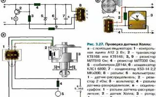
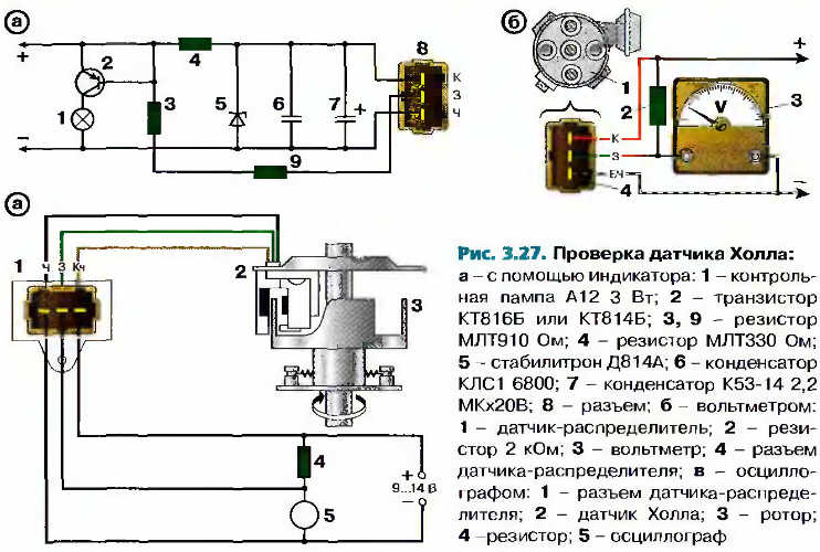
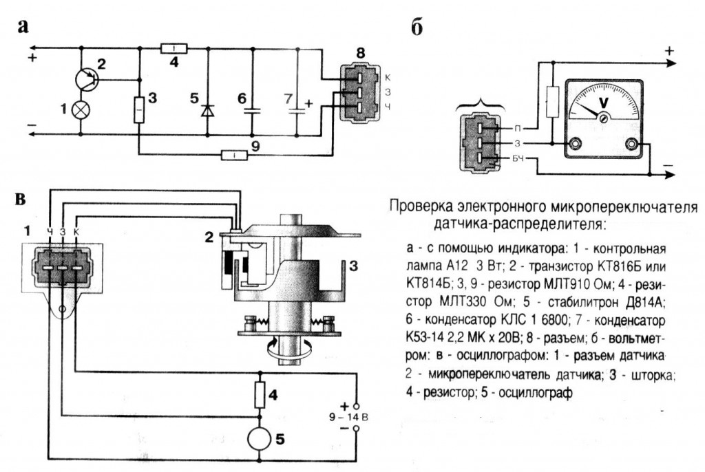
Checking the serviceability of the hall sensor (diagram)
- Creating a simulation of the presence of a Hall sensor . This method of checking is the fastest and is suitable if there is power at the ignition system components, but there is no spark. For this purpose, the three-pin block is removed from the distributor. Next, you need to turn on the car’s ignition and connect (short with a piece of wire) outputs 3 and 2 (negative pin and signal contact). If during this process a spark appears , it means the sensor has failed . Please note that in order to detect sparking, you need to hold the high-voltage wire near ground.
- Checking the Hall sensor with a multimeter is the most common method. For this check, a multimeter (tester) is used. To do this, it is enough to measure the voltage at the output of the sensor. then the voltage should be within 0.4...11 V.
- Replacing a faulty device with a known working one . You can borrow it from friends who have a car with the same sensor. If after replacement the problems that bother you disappear, you will have to buy and replace the Hall sensor with a new one.
Hall sensor check
Hall sensor, checked with a multimeter.
Another common method is to check for resistance at the sensor . To do this, you need to make a simple device consisting of a 1 kOhm resistor, an LED and flexible wires. A resistance is soldered to the LED leg, and two wires of a length that is convenient for operation (not short) are soldered to it.
Then remove the distributor cover, disconnect the distributor and plug box. Next, check the serviceability of the electrical circuit. To do this, an electronic multimeter (voltmeter) is connected to terminals 1 and 3, after which the car’s ignition is turned on. Under normal conditions, the value obtained on the screen of the measuring device should be within 10...12 V.
Next, we similarly connect the constructed device to the same terminals. If you guessed the polarity correctly, the LED lights up. Otherwise, the wires must be swapped. The further procedure is as follows:
- do not touch the wire connected to the first terminal;
- We transfer the end from the third terminal to the free second;
- rotate the camshaft (manually or using a starter).
If the LED blinks while the shaft is turning, then everything is in order and the Hall sensor does not need to be replaced.
It is worth noting that the process of checking the Hall sensor on the VAZ 2109, Audi 80, Volkswagen Passat B3 and other cars is carried out according to the same scheme. The only difference is the location of individual parts under the hood of the car.
Hall sensor replacement
Replacing the Hall sensor VAZ 2109
Let's consider the process of replacing the Hall sensor on a VAZ 2109 car . This procedure is simple and does not cause difficulties even for novice car enthusiasts. Its algorithm is as follows:
- The first step is to remove the distributor from the car.
- After this, the distributor cover is dismantled. Next, you need to align the marks of the timing mechanism and the crankshaft mark.
- Then the fasteners are dismantled using a wrench. At the same time, do not forget to mark and remember the location of the distributor.
- If there are latches or stoppers in the housing, they must also be removed.
- At the next stage, remove the shaft from the distributor.
- Next, disconnect the Hall sensor terminals and unscrew the mounting bolts.
- The sensor is removed through the resulting gap.
- Installation of a new Hall sensor is carried out in the reverse order.
Conclusion
It is worth noting that there is no point in repairing the Hall sensor, since it is very inexpensive (about $3...5).
If you are convinced that the car’s malfunctions are related specifically to the mentioned sensor, we recommend that you go to the nearest auto store and buy a new device.
If you encounter any difficulties when checking or replacing the Hall sensor, please contact the technicians working at the service station for help.
Did not find an answer to your question?
Ask in the comments. We will definitely answer!
Source: https://etlib.ru/blog/526-kak-proverit-datchik-holla
How to check the hall sensor using a tester (voltmeter)
Many motorists today are interested in the issue of high-quality testing of the hall sensor - the mini-regulator of the ignition distributor of modern cars.
Having learned to do this yourself, you can safely go on long trips without fear of finding yourself helpless in front of a car alone.
A classic test of a hall sensor using a DC measuring device is presented in the article.
The role of the sensor in the SZ system
ATTENTION! A completely simple way to reduce fuel consumption has been found! Don't believe me? An auto mechanic with 15 years of experience also didn’t believe it until he tried it. And now he saves 35,000 rubles a year on gasoline! Read more"
If the sensor or DC malfunctions, problems arise related to the direct functioning of the engine. The car may not start at all or behave extremely poorly on the road. Is it really possible for such a small element as DH to have such a powerful effect on a car’s engine? Yes, yes.
What is DH? This is a controller capable of sensitively responding to any changes in the magnetic field. If the DC is faulty, the injector stops functioning.
The interaction of the DC with the ignition system in the electrical sense is carried out through a switch or conductor. As a result, a magnetic field appears.
Checking the sensor with a multimeter
You can check the DH in different ways. One popular diagnostic option is a multimeter or voltmeter. This verification method has two options. Let's look at how to check a car's hall sensor in both cases.
1st method
To carry out diagnostics, you need to find a working voltmeter or multimeter that is set to measure DC voltage (direct current) in the range of 20 Volts. In addition, you will need to stock up on 2 iron pins, through which the DC will be checked.
Multimeter for checking the hall sensor
Before checking the hall sensor, you will need to remove the rubber boot from the block, which is connected to the distributor and directly to the DH.
Let's continue:
- remove the main armored wire from the distributor;
- We connect it to the arrester or to ground.
This is done in order to exclude the accidental occurrence of a discharge, because this may contribute to starting the engine during the test.
Further:
- turn on the ignition;
- remove the block from the distributor;
- set the mode on the multimeter to DC 20 V;
- We connect the negative terminal of the device to ground (any part of the car body);
- the positive probe of the device will serve as a voltage meter.
The block going to the distributor has three wires: red, green and white (colors may be different). On the red wire, the voltage of the device should show 11.37 or close to 12 V. On the green or middle wire, the value is also close to 12 V. And finally, on the last - white wire, the value is 0.
Functions of a modern multimeter
By the way, if you put the device in the audio test mode, then placing the probe on the contact, you will hear a constant ringing, which will indicate that the white wire is connected to ground. That's how it should be.
What did the preliminary check give? We made sure that the households received all the necessary impulses.
Continue (multimeter in DC measurement mode):
- We take the prepared pins (studs) and thread them like this: one into the green (middle wire), the other into the white (ground wire);
- We connect the block in its place, in the car distributor.
Why are pins needed? They play the role of a current conductor. There are no contacts on the back of the block, and the values can only be checked if the wires are exposed. This is not recommended, which is why the pins are inserted.
Go ahead:
- take the multimeter clamps (ignition is on);
- We connect the positive terminal of the multimeter to the pin of the middle wire of the block, and the negative terminal to the other (white wire).
Indicator of non-working sensor
In this position, the multimeter value should be within 11.2 V.
Further:
- crank the crankshaft while simultaneously observing the instrument readings;
- if the instrument readings drop to 0.02 V (lower measurement limit) and rise to 11.8 V (upper measurement limit) when cranking the crankshaft, then this is considered normal.
Thanks to these measurements, we checked the performance of the DC installed in the car distributor.
2nd method
The second verification method differs from the first in that this time the DH is diagnosed autonomously. In other words, it will not be connected to the ignition system - to the switch.
So, to carry out this method you will need a homemade assembly of 3 contacts inserted into the distributor block, plus/minus pins and 2 test points for measurements. The homemade assembly diagram will look like this
Here's what to do:
- Connect the three homemade contacts to the connectors where the original distributor block is inserted (if the sensor is removed, then to its terminals);
- supply plus/minus power to the homemade assembly;
- connect the plus of the multimeter to one control point for measurement, the minus to the other;
- turn the crankshaft.
Again, the upper limit of measurement on a working sensor should not be lower than 9 V, and the lower limit should not be higher than 0.4 V.
If the DH is removed from the car, then it will be checked as follows:
- the sensor leads are connected to the homemade assembly (the other connections are the same as in the case described above);
- take a knife or curtain and draw the blade along the slot in the DH.
When the curtain is closed, the DC readings are above 9 V, and when the curtain is open, they are below 0.4 V.
Thus, using a multimeter, you can check the DC for serviceability in 2 simple ways. Of course, there are many other options for checking the sensor, but they are more difficult to carry out, although they provide instant access to the DH.
Hall sensor ignition circuit
A general familiarity with the operating principle of DCs, despite the gradual displacement of contactless ignition systems by multiprocessor ones, will provide many benefits in the future. So, this can help the car owner when using other car sensors that operate on the Hall principle: speed sensor, camshaft position, etc.
Tired of paying fines? There is an exit!
Forget about fines from cameras! An absolutely legal new product - NANOFILM, which hides your license plates from IR cameras (which are installed in all cities). More details at the link.
- Absolutely legal (Article 12.2.4).
- Hides from photo and video recording.
- Installs independently in 2 minutes.
- Invisible to the human eye, does not deteriorate due to weather.
- 2 year warranty
Source: http://ozapuske.ru/holl/kak-proverit-datchik-xolla.html
How to check the Hall sensor
Modern machines use a special device to measure rotation speed - a Hall sensor. Its functioning is a very important process. A malfunction of such a device means that the car can no longer be started using the starter.
This explains why many motorists want to know how to test a Hall sensor. In order to assess the serviceability of the device, you must first learn about how it works.
How does a Hall sensor work?
The operation of the Hall regulator occurs due to a phenomenon called the “Hall effect”. With it, an electric field is created due to the fact that a transverse magnetic field acts on the semiconductor, under load conditions.
At this time, current passes through the semiconductor. The voltage ranges from 0.4–3 volts.
In pulse mode, the regulator begins to operate if periodic shielding of the magnetic field source occurs. To do this, each simple Hall sensor has a circular screen on which there are slots or ferromagnetic curtains. There are as many curtains as there are cylinders. When should you check?
Discounts on new cars! Advantageous loan from 9.9%
Installment plan 0%
So, what “symptoms” will tell us that the Hall device has failed? The most common options are:
- too much fuel consumption;
- increase in engine operating temperature;
- the corresponding indicator on the dashboard lights up;
- when the engine is idling, interruptions and jerking appear;
- the power unit stalls while driving;
- the engine is difficult (or impossible) to start.
However, the most common are the first three “symptoms”. Therefore, let us pay special attention to them.
Too much fuel consumption
The increase in gas or gasoline consumption should be sharp and sudden. In the event that you know how much fuel your car consumes when covering a certain distance, and suddenly these numbers have increased, among other things, check the device we are talking about.
What is happening may indicate a malfunction of the device or that it is gradually beginning to fail.
Increasing engine operating temperature
The engine begins to heat up more than usual regularly if the device is faulty. With such “symptoms” you need to act as soon as possible.
Such malfunctions can lead to serious problems in the engine parts of the car.
The corresponding indicator on the dashboard lights up
Most modern cars are equipped with a quite convenient dashboard, on which there are indicators that inform the driver about any problems.
If you have such a panel, you just need to be careful. If the device begins to malfunction, the burning “light” will immediately inform the motorist about this.
Checking the sensor
There are so many ways to check these devices that every motorist on this list will certainly be able to choose the one that suits him. Most often, car owners use the following methods:
- checking with a voltmeter;
- verification using analogue;
- verification by simulation;
- checking with LED.
Checking with a voltmeter
Checking the Hall sensor using a voltmeter is as follows: connect the device to the device itself and look at its indicators.
We already know what voltage is optimal for the device (0.4–3 volts). If the readings are lower, it means the device is faulty and will have to be replaced.
Checking with another sensor
A check performed using another device may be quite effective. Only you must be 100% sure of the serviceability of this analogue.
We remove the old device and install a new one in its place. And see if the problems disappear when you change the device.
We will talk later about how to replace the Hall sensor.
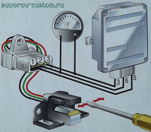
Verification using simulation
To do this, you should assemble a device that can simulate the operation of the device. If you decide to use this method, take the three-pin block available from the ignition distributor and a piece of wire.
We turn on the ignition, and bring the end of the wire to the switch outputs located at numbers 3 and 6.
If it does not spark, then the device is in order. But if at least one spark appears, then the device will have to be replaced.
Checking with LED
This method was invented by folk craftsmen. Anyone who knows how a soldering iron works can make a testing device. What you will need:
- soldering iron;
- resistance at 1 kOhm;
- regular LED;
- two thin wires (must be insulated).
We solder the resistance to the light bulb. We attach two wires to it. The ends of the wires should be slightly exposed.
Let's start checking. We remove the distributor cover, the plug box must be disconnected. We connect a diode to terminals numbered 1 and 3. If the light comes on, it means the wiring is installed correctly. If not, swap them.
Then we leave the wiring on terminal 1 in place, and transfer the other one to the second terminal. Using the starter, slowly turn the camshaft. If the light does not go out completely and does not light continuously, but blinks, then the device is in order. Otherwise, it should be professionally inspected.
Changing the Hall sensor
Now you have already checked the sensor and may have discovered that it is faulty.
This means you need to change this device. Most likely, replacing the Hall sensor will not cause you any trouble, since an amateur can handle it, but to do this you will have to disassemble the ignition system breaker-distributor. What you will need to replace:
- pliers;
- keys for 13, 10, 8, 7, 6 millimeters;
- screwdriver.
Getting to the sensor
Using a 13 mm wrench, unscrew the nut that presses the distributor fork. The bracket needs to be removed. Remove the cover from the high voltage distributor. Then you should mark the location of the “slider”. Now you can get the breaker-distributor.
An oil deflector cap is secured to the drive shaft with a pin. This pin should be knocked out. Then the parts will separate.
There are two mounting screws on the vacuum ignition timing mechanism. They need to be unscrewed using a screwdriver. After this, the rod can be disconnected from the movable disk of the breaker.
Now, by unscrewing two more screws on the distributor body, you can remove the Hall sensor.
Changing the sensor
After the faulty device has been removed, you need to remove it and replace it with a new device. Now you can assemble the distributor. To do this, you need to do all the above steps in reverse order.
After the old sensor has been replaced by a new device, its serviceability should also be checked using one of the methods already described in the article. If you see any signs of trouble again, check that you installed the new sensor correctly. If your own examination does not yield results, contact professionals.
Source: http://CarExtra.ru/sovety/kak-proverit-datchik-holla.html
Do-it-yourself repair of distributor and Hall sensor
The information is applicable to repairing many vehicles.
The idea is not new, and not mine, but I decided to show it in pictures. It happens that the Hall Sensor stops working normally - then the car may either not start at all, or it starts according to the mood and works at random intermittently (that is, there is a spark, then there is no). It can be repaired very cheaply (a chip costs less than $1).
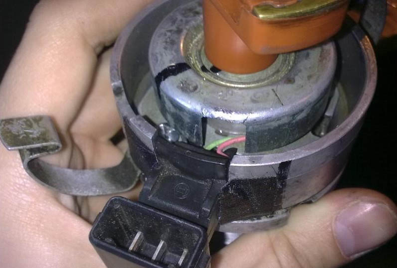
The removed sensor from 5-cylinder Audi 2.0 ... 2.3 engines (this particular sensor from the Audi 100 C4, AAR engine) looks like this:
To check it, you need to connect the +12 battery to the red wire, “-“ to the brown wire, and between green and red - a multimeter in direct voltage (DC) measurement mode (or an LED that will light up and go out).
In this case, the multimeter will show about 12V, and when the gap between the magnet and the sensor is blocked with a metal plate - 0V. Moreover, even if you tap on the sensor, everything should work stably.
Faulty ones will either not work at all, or depend on a blow to them and turn on every other time. A faulty sensor must be replaced.
You can buy a new sensor assembly that will fit perfectly into the Huco 13 8156 - but its price tag is higher than the price of a new distributor assembly (Chinese Patron P41-0002 ) - and this will not make you very happy. We need a cheap solution and we have it.
🙂
But first you need to remove it from the distributor. To do this, you need to either knock out the pin with a high-quality drift and then the shaft will be removed, or knock the shaft away from the curtain from above (or place a pipe underneath and use inertia to “remove” the shaft).
First make marks on the curtain so that you can mutually orientate it later:
The curtain just sits on the teeth. You can see what it all looks like below:
By the way, for some reason it was not possible to completely stuff the curtain into its previous position; for some reason it was not clogged by about 0.3-0.4 mm. This will not affect the operation, the sensor is already triggered, but it is still better to first try to knock out the pin, and if it no longer works, then only then leave the pin in place and knock the shaft away from the curtain.
The plate with the sensor in your hands - cut off the wires with a knife:
Then we fix the plate in a vice and drill out the old DH. A simple drill can easily drill through plastic, but when it gets to the chip, the drill will become dull and it wouldn’t hurt to have some attachments or drills made of stronger metal. I was able to drill deep only with the top nozzle):
It is important to reach the depth where the new chip is opposite the magnet. This is the hollow I continued:
As for the chip itself, I bought a hall sensor with the article number “3144” from radio components (you can also use “SS441A”, probably others). Its appearance and pinout are here:
You can also check (as described above) by bringing a magnet in and out.
Solder according to the wire pinout (+heat shrink):
And we push the DH into its hollow (the side with the inscription “3144” is closer to the magnet):
I filled it with Russian ordinary epoxy - it will hold it well and insulate it from moisture:
The wires are placed under protective plastic. I coated the chip with a little sealant so that the wiring would not “move out” and stay in the chip:
“Hint” from VAGa, where the pinout is also indicated:
Well, then the assembly:
There is still a thin washer under the curtain:
Filled the curtain:
How to insert a distributor into the motor and configure the UZ without a strobe is written here.
I also have a distributor with a working original DH - but I decided to restore the old distributor that had failed - and I succeeded.
It works great, the cost of the chip is less than $1 - what we need for our cars, which are getting cheaper by $$$$. I use this DH with radio components. Write additions about your experience of using it.
Continuation and all discussions of the report here
Thanks: Jurik-11
Decoding of the factory equipment of the car (English)
Decoding of the factory equipment of VAG
Diagnostics of Volkswagen, Audi, Skoda, Seat, error codes.
If you have not found information on your car, look at the cars built on the platform of your car.
Most likely, the information on repair and maintenance will be suitable for your car.
Source: http://vwts.ru/articles/ignition/remont-tramblera-datchik-holla.html
What is a Hall sensor in a car, its connection, symptoms and troubleshooting
Home page » Timing belt » What is a Hall sensor in a car, its connection, symptoms and troubleshooting
The device is used instead of contact elements and can be used to monitor the load current. Thanks to this sensor, the engine is deactivated when current overloads occur in the on-board network. If the controller overheats, temperature protection is activated.
Principle of operation
Voltage surges in the motor electrical network can have consequences for the sensor. Therefore, modern devices are additionally equipped with diode elements that prevent reverse voltage activation.
The operating principle of the device is based on the Hall effect. A transverse potential difference is formed when one of the conductors moves into a magnetic field.
This effect is achieved due to the fact that currents pass through the terminal elements of the plate, which is located in the field itself, with the semiconductor.
When the engine is running and the power unit shaft rotates, the steel blades move along special slots installed inside the housing.
This helps to supply an electrical signal to the switching device. As a result, the node opens the transistor element and supplies voltage to the coil.
The latter performs the procedure of converting a low-voltage pulse into a high-voltage one. This signal is sent to the spark plugs.
The Radio Amateur TV channel spoke in detail about the principle of operation of the Hall controller.
Where is it located and what does it look like?
If it is necessary to replace a faulty device, the consumer needs to know where the controller is located. It is located in the car distributor and is made in the body in the form of a small cylindrical element.
To gain access to the device, it is necessary to disassemble the distribution unit and remove the cover, slider and other parts of the mechanism.
On the outside of the distributor, a connector with wiring is connected to the Hall controller.
Device
The optical camshaft position regulator is designed as follows:
- 1 - permanent magnetic device;
- 2 — blade of the rotor mechanism;
- 3 - magnetic circuits;
- 4 - plastic case, which contains all elements of the device;
- 5 - board;
- 6 - contact pins.
Hall controller adaption diagram
The device is equipped with three contacts:
- the first is used to connect to ground, that is, the car body;
- the second is necessary to connect positive voltage, the operating parameter of which is approximately 6 volts;
- the third contact is intended to send an impulse from it to the switching device.
What malfunctions can there be?
Symptoms of Hall controller problems:
- There is a sharp increase in fuel consumption in the system. This is due to the fact that the injection of the combustible mixture into the power unit occurs more than once per cranking cycle.
- The car's engine began to function less stable. The vehicle jerks while driving, and engine power may drop sharply. Sometimes it is not possible to increase the speed of the car by more than 60 km/h. While driving, the power unit may randomly stall.
- Sometimes a Hall sensor failure causes the transmission lever to lock. It is impossible to change the gearbox speed; this feature is typical for new foreign cars. To solve the problem, you need to restart the power unit.
- A malfunction may manifest itself in the form of a lack of spark to ignite the combustible mixture. Because of this, starting the car engine will be impossible.
- There may be malfunctions in the functioning of the self-diagnosis system. For example, an engine check indicator appears on the control panel if the unit is idling. When the engine speed increases, the error message disappears from the dashboard.
The Auto-Moto channel talked about signs of a faulty regulator, as well as other elements of the ignition system in a car.
If the Hall controller itself is intact and working, then the malfunction may be due to the following reasons:
- There is dirt or other foreign objects on the device body.
- The signal cable through which the controller is connected is damaged or broken.
- Moisture has entered the block for connecting the Hall sensor to the on-board network. The problem can be solved by drying the connector.
- There is a short circuit between the signal conductor and the vehicle body or electrical network. To determine the malfunction, you need to ring the device.
- The shielding component on the wiring harness has been damaged. Individual cables may break.
- The problem may be damage to the conductors intended to power the Hall controller.
- The polarity was reversed when connecting the device. Because of this, the sensor does not function correctly or does not work at all.
- Malfunctions in the functioning of the high-voltage circuit of the ignition system.
- Problems in the functioning of the vehicle control module.
- When installing the controller, the backlash between the sensor itself and the magnetic conductive plate was incorrectly set.
- The problem may lie in the increased amplitude of the end action of the camshaft gear. Detailed diagnostics of the circuit is required.
Dmitry Maznitsyn in the video talked about the reasons for the regulator malfunction and gave recommendations for eliminating them.
Sensor check
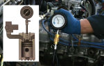
There are several ways to diagnose a controller. The most accurate option that will allow you to obtain an oscillogram is to use special equipment.
An oscilloscope will not only determine the state of the controller, but will also make it clear that the device will soon fail.
Not every electrician has such equipment, so simpler, but no less effective options are discussed below.
Diagnostics with a multimeter
Before testing, the device must be set to DC measurement mode, the operating range should be 20 volts. You will also need two metal pins. Before carrying out diagnostics, the rubber cover is removed from the device connector.
The preliminary check procedure to determine that the necessary signals are supplied to the Hall controller is performed as follows:
- The main armored wire is disconnected from the distribution unit. It must be connected to the vehicle ground to prevent accidental discharge. Because this will cause the power unit to start during diagnosis.
- Then the ignition system is activated.
- The connector is disconnected from the distribution mechanism.
- The tester is set to DC mode with a range of 20 volts.
- The negative contact of the multimeter is connected to the car body, you can choose any place. The positive output of the tester will be used to measure the operating voltage parameter.
- The connector connected to the distribution unit is equipped with three contacts - red, green and white, but the colors of the conductors may be different. At the first output the voltage value should be 11.37 volts or about 12 V, at the second output it should also be around this value. And on the last conductor the operating parameter should be 0 volts.
Next stage of diagnosis:
- Take two metal pins, you can use nails. One of them is installed in the middle contact of the block (usually green), and the other is connected to ground. Its color is usually white. The connector itself is then connected back to the switchgear. The pins are used as current conductors. There are no open contacts on the back of the connector, so to check the cables themselves you will have to expose them, and this is not recommended.
- The ignition is then activated. The positive contact of the tester must be connected to the middle output pin on the connector, and the negative contact to the white conductor. The voltage is measured. If the Hall controller is working, then the resulting value should be about 11.2 volts.
- Then you need to rotate the crankshaft of the power unit and at the same time check the indicators that the tester gives. If the values decrease to 0.02 volts during cranking and then increase to 11.8 V, then this is normal. This is how it should be in the lower and upper limits of measurements. You can turn off the tester.
The Hall controller is considered working if, when cranking the crankshaft, the upper measurement limit is not lower than 9 volts, and the lower limit is not higher than 0.4 V.
The “Autoelectrics HF” channel showed in detail the procedure for diagnosing a sensor using a tester and talked about the main features of this process.
Resistance check
To diagnose this parameter, you will need a simple device consisting of a 1 kOhm resistor element, a diode light bulb, and flexible cables. A resistor must be connected to the leg of the light source; soldering is used for reliable fixation. Two conductors of the required length are connected to this part; it is important that they are not short.
The verification principle looks like this:
- The distribution mechanism cover is being dismantled. The distributor itself is disconnected from the contacts, as well as the block with wires.
- Diagnostics of the health of the electrical circuit is performed. To do this, the tester must be connected to the first and third terminals, and then activate the ignition. If all conductors are intact, then the voltage on the multimeter display will be from 10 to 12 volts.
- Then, in the same way, the assembled device is connected to the same outputs. When the polarity is correct, the diode light will light up; if not, then the cables must be swapped.
- Then the conductor connected to the first output remains untouched. And the end of the third terminal switches to the second. The camshaft is being rotated. This can be done by hand or using a starter mechanism.
- If during these actions the light source begins to blink, then the controller is working correctly and does not need to be replaced.
The Altevaa TV channel talked about a way to check the sensor using a regular light bulb using the example of a Volkswagen car.
Creating a Hall Controller Simulation
This option for diagnosing the Hall sensor is considered the fastest, but its implementation is possible if there is power in the ignition system and there is no spark.
The three-pin connector is disconnected from the distribution mechanism.
The ignition in the car is activated and, using a piece of conductor, contacts numbered 2 and 3 are closed, these are the signal outputs and pin.
If, as a result of the connection, a spark is formed on the central cable, this indicates a breakdown of the Hall controller. When performing the task, the high-voltage conductor must be kept near the ground of the car.
Trouble-shooting
The repair is considered using a Volkswagen car as an example.
To restore functionality, the sensor can be repaired:
- To restore controller operation, the logic component must be replaced. To do this, you need to purchase the S441A device in advance.
- In the central part of the sensor body, as shown in the photo, a small hole is drilled using a drill. This will require a high-quality drill, since there is a metal frame inside the controller, behind the plastic part.
- Using a utility knife, you need to cut off each conductor. Then grooves are laid from the hole made using a file to the remaining cables.
- The measuring device itself is mounted in the housing window. A magnet is used for diagnostics. If you attach this element to the contacts to which a device consisting of a diode light bulb and a resistor is previously connected. This device was used for diagnostics. As a result of the test, the lamp should light up. If this does not happen, then you need to check the polarity.
- Then the leads are routed along the grooves of the housing. In the window itself, you must leave the conductors for the connecting block of the new controller. The elements are soldered.
- At the final stage, the completed actions are checked. A tester is used for this. It is necessary to visually verify the integrity of all contacts. If the device is working, then the mechanism is sealed using glue or another composition, but not plastic. This material can become deformed when working at elevated temperatures.
- The controller is being assembled, all actions are carried out in the reverse order.
Connecting contacts to element S441A Place for drilling the device body Installing the device in a distribution unit
How to replace the sensor yourself?
To change the controller, you need to do this:
- The terminal clamps are disconnected from the car battery.
- The distribution mechanism is being dismantled. The block with conductors is disconnected from the device, the bolts securing the unit are unscrewed.
- The distributor cap is being removed. Depending on the distributor model, it can be fixed with bolts or special clamps. The fastening elements are unscrewed and dismantled.
- After removal, it is important to align the mark of the gas distribution device with the mark on the crankshaft of the power unit. It is also necessary to remember the position of the distribution unit. It is recommended to make a corresponding mark before removal.
- The housing fastening elements are unscrewed using a wrench. The clamps are dismantled if they are installed on the mechanism.
- The shaft is removed from the distribution unit.
- The clamps with terminals are disconnected from the Hall controller.
- The sensor is removed from the mounting location. To carry out the task, the device must be pulled towards you and carefully removed. The sensor is dismantled through the hole that appears.
- A new controller is taken and installed in place of the old one. The installation procedure is performed in reverse order.
Video “Consequences of incorrect installation of the Hall sensor”
User Uncle Sasha explained what could result from incorrect installation of the device and gave recommendations on how to fix this problem.
Do you have any questions? Specialists and readers of the AUTODVIG website will help you ask a question
Source: https://autodvig.com/grm/chto-takoe-datchik-holla-64849/