How to charge a car battery
Battery problems are not that uncommon. To restore functionality, additional charging is necessary, but normal charging costs a lot of money, and it can be done from available “trash.”
The most important thing is to find a transformer with the required characteristics, and making a charger for a car battery with your own hands takes just a couple of hours (if you have all the necessary parts).
A little theory
The battery charging process must follow certain rules. Moreover, the charging process depends on the type of battery. Violations of these rules lead to a decrease in capacity and service life.
Therefore, the parameters of a car battery charger are selected for each specific case. This opportunity is provided by a complex charger with adjustable parameters or purchased specifically for this battery.
There is a more practical option - making a charger for a car battery with your own hands. To know what parameters should be, a little theory.
Before starting charging, you need to measure the voltage
Types of battery chargers
Battery charging is the process of restoring used capacity. To do this, a voltage is supplied to the battery terminals that is slightly higher than the operating parameters of the battery. Can be served:
- D.C. The charging time is at least 10 hours, during this entire time a fixed current is supplied, the voltage varies from 13.8-14.4 V at the beginning of the process to 12.8 V at the very end. With this type, the charge accumulates gradually and lasts longer. The disadvantage of this method is that it is necessary to control the process and turn off the charger in time, since when overcharging the electrolyte may boil, which will significantly reduce its working life.
- Constant pressure. When charging with a constant voltage, the charger produces a voltage of 14.4 V all the time, and the current varies from large values in the first hours of charging to very small values in the last. Therefore, the battery will not be recharged (unless you leave it for several days). The positive aspect of this method is that the charging time is reduced (90-95% can be reached in 7-8 hours) and the battery being charged can be left unattended. But such an “emergency” charge recovery mode has a bad effect on service life. With frequent use of constant voltage, the battery discharges faster.
Graphs of changes in memory parameters in different modes
In general, if there is no need to rush, it is better to use DC charging. If you need to restore battery functionality in a short time, apply constant voltage.
If we talk about what is the best charger to make for a car battery with your own hands, the answer is clear - one that supplies direct current.
The schemes will be simple, consisting of accessible elements.
How to determine the necessary parameters when charging with direct current
It has been experimentally established that to charge car lead-acid batteries (the majority of them) with a current that does not exceed 10% of the battery capacity .
If the capacity of the battery being charged is 55 A/h, the maximum charge current will be 5.5 A; with a capacity of 70 A/h - 7 A, etc. In this case, you can set a slightly lower current. The charge will continue, but more slowly. It will accumulate even if the charge current is 0.1 A.
It will just take a very long time to restore capacity.
Since the calculations assume that the charge current is 10%, we obtain a minimum charge time of 10 hours. But this is when the battery is completely discharged, and this should not be allowed. Therefore, the actual charging time depends on the “depth” of the discharge. You can determine the depth of discharge by measuring the voltage on the battery before charging:
- A fully charged battery (100%) has a voltage of 12.7-12.8 V.
- Half discharge (about 50%) with a voltage of 12 V. At this level or slightly lower, you need to put the battery on charge.
- Almost full or full discharge (10-0%) - 11.8-11.7 V. It is better not to drop to such values - frequent full discharge shortens the service life. Each manufacturer will have its own specific voltage, but you can roughly navigate using these data (Bosch batteries)
To calculate the approximate battery charging time , you need to find out the difference between the maximum battery charge (12.8 V) and its current voltage. Multiplying the number by 10 we get the time in hours.
For example, the voltage on the battery before charging is 11.9 V. We find the difference: 12.8 V - 11.9 V = 0.8 V. Multiplying this figure by 10, we find that the charging time will be about 8 hours.
This is provided that we supply a current that is 10% of the battery capacity.
Charger circuits for car batteries
To charge batteries, a 220 V household network is usually used, which is converted to reduced voltage using a converter.
Simple circuits
The simplest and most effective way is to use a step-down transformer. It is he who lowers 220 V to the required 13-15 V. Such transformers can be found in old tube TVs (TS-180-2), computer power supplies, and found at flea market “ruins”.
But the output of the transformer produces an alternating voltage that must be rectified. They do this using:
- One rectifying diode, which is installed after the transformer. At the output of such a charger, the current turns out to be pulsating, and the beats are strong - only one half-wave is cut off. The simplest circuit
- A diode bridge that “turns” the negative wave upward. The current is also pulsating, but there is less beat. It is this scheme that is most often implemented independently, although it is not the best option. You can assemble a diode bridge yourself using any rectifying diodes, you can buy a ready-made assembly. Do-it-yourself charger for a car battery: circuit with a diode bridge
- Diode bridge and smoothing capacitor (4000-5000 µF, 25 V). At the output of this circuit we obtain a direct current. Circuit with a smoothing capacitor
The above diagrams also contain fuses (1 A) and measuring instruments. They make it possible to control the charging process. They can be excluded from the circuit, but you will have to periodically use a multimeter to monitor them.
With voltage control this is still tolerable (just attach probes to the terminals), but it is difficult to control the current - in this mode the measuring device is connected to an open circuit. That is, you will have to turn off the power every time, put the multimeter in current measurement mode, and turn on the power.
disassemble the measuring circuit in reverse order. Therefore, using at least a 10 A ammeter is very desirable.
The disadvantages of these schemes are obvious - there is no way to adjust the charging parameters. That is, when choosing an element base, choose the parameters so that the output current is the same 10% of the capacity of your battery (or a little less). You know the voltage - preferably within 13.2-14.4 V.
What to do if the current turns out to be more than desired? Add a resistor to the circuit. It is placed at the positive output of the diode bridge in front of the ammeter.
You select the resistance “locally”, focusing on the current; the power of the resistor is larger, since excess charge will be dissipated on them (10-20 W or so).
And one more thing: a do-it-yourself car battery charger made according to these schemes will most likely get very hot. Therefore, it is advisable to add a cooler. It can be inserted into the circuit after the diode bridge.
Adjustable circuits
As already mentioned, the disadvantage of all these circuits is the inability to regulate the current. The only option is to change the resistance. By the way, you can put a variable tuning resistor here. This will be the easiest way out. But manual current adjustment is more reliably implemented in a circuit with two transistors and a trimming resistor.
Circuit diagram of a charger for a car battery with the ability to manually adjust the charge current
The charging current is changed by a variable resistor. It is located after the composite transistor VT1-VT2, so a small current flows through it. Therefore, the power can be about 0.5-1 W. Its rating depends on the selected transistors and is selected experimentally (1-4.7 kOhm).
Transformer with a power of 250-500 W, secondary winding 15-17 V. The diode bridge is assembled on diodes with an operating current of 5A and higher.
Transistor VT1 - P210, VT2 is selected from several options: germanium P13 - P17; silicon KT814, KT 816. To remove heat, install on a metal plate or radiator (at least 300 cm2).
Fuses: at the input PR1 - 1 A, at the output PR2 - 5 A. Also in the circuit there are signal lamps - the presence of a voltage of 220 V (HI1) and a charging current (HI2). Here you can install any 24 V lamps (including LEDs).
Video on the topic
DIY car battery charger is a popular topic for car enthusiasts. Transformers are taken from everywhere - from power supplies, microwave ovens... they even wind them themselves. The schemes being implemented are not the most complex. So even without electrical engineering skills you can do it yourself.
Source: https://elektroznatok.ru/oborudovanie/zaryadnoe-ustrojstvo-dlya-avtomobilnogo-akkumulyatora-svoimi-rukami
Circuit diagram of a charger for a car battery - from simple to complex
Under normal operating conditions, the vehicle's electrical system is self-sufficient.
We are talking about energy supply - a combination of a generator, a voltage regulator, and a battery works synchronously and ensures uninterrupted power supply to all systems.
This is in theory.
In practice, car owners make amendments to this harmonious system. Or the equipment refuses to work in accordance with the established parameters.
For example:
- Operating a battery that has exhausted its service life. The battery does not hold a charge
- Irregular trips. Prolonged downtime of the car (especially during hibernation) leads to self-discharge of the battery
- The car is used for short trips, with frequent stopping and starting of the engine. The battery simply does not have time to recharge
- Connecting additional equipment increases the load on the battery. Often leads to increased self-discharge current when the engine is turned off
- Extremely low temperature accelerates self-discharge
- A faulty fuel system leads to increased load: the car does not start immediately, you have to turn the starter for a long time
- A faulty generator or voltage regulator prevents the battery from charging properly. This problem includes worn power wires and poor contact in the charging circuit.
- And finally, you forgot to turn off the headlights, lights or music in the car. To completely discharge the battery overnight in the garage, sometimes it is enough to close the door loosely. Interior lighting consumes quite a lot of energy.
Any of the above reasons leads to an unpleasant situation: you need to drive, but the battery is unable to crank the starter. The problem is solved by externally feeding the battery: that is, a charger.
It is absolutely easy to assemble it with your own hands. An example of a charger made from an uninterruptible power supply.
Any car charger circuit consists of the following components:
- Power unit.
- Current stabilizer.
- Charge current regulator. Can be manual or automatic.
- Indicator of current level and (or) charge voltage.
- Optional - charge control with automatic shutdown.
Any charger, from the simplest to an intelligent machine, consists of the listed elements or a combination thereof.
Circuit diagram of a simple charger for a car battery
The formula for a normal charge is as simple as 5 kopecks - the basic battery capacity divided by 10. The charging voltage should be a little over 14 volts (we are talking about a standard 12 volt starter battery).
A simple circuit diagram of a car charger consists of three components : power supply, regulator, indicator.
Classic - resistor charger
The power supply is made of two winding “trans” and a diode assembly. The output voltage is selected by the secondary winding. The rectifier is a diode bridge; a stabilizer is not used in this circuit.
The charging current is controlled by a rheostat.
A wire rheostat is necessary to counteract the main problem with such a circuit - excess power is released in the form of heat. And this happens very intensively.
Of course, the efficiency of such a device tends to zero, and the service life of its components is very low (especially the rheostat).
Nevertheless, the scheme exists, and it is quite workable. For emergency charging, if you don’t have ready-made equipment at hand, you can literally assemble it “on your knees.” There are also limitations - a current of more than 5 amperes is the limit for such a circuit. Therefore, you can charge a battery with a capacity of no more than 45 Ah.
DIY charger, details, diagrams - video
Quenching capacitor
The operating principle is shown in the diagram.
Thanks to the reactance of the capacitor included in the primary winding circuit, the charging current can be adjusted. The implementation consists of the same three components - power supply, regulator, indicator (if necessary). The circuit can be configured to charge one type of battery, and then the indicator will not be needed.
If you add one more element - automatic charge control , and also assemble a switch from an entire battery of capacitors - you get a professional charger that remains easy to manufacture.
The charge control and automatic shutdown circuit does not need any comments.
The technology has been proven, you can see one of the options in the general diagram. The response threshold is set by variable resistor R4. When the own voltage at the battery terminals reaches the configured level, relay K2 turns off the load.
An ammeter acts as an indicator, which stops showing the charge current.
The highlight of the charger is the capacitor battery.
The peculiarity of circuits with a quenching capacitor is that by adding or decreasing capacitance (simply connecting or removing additional elements) you can regulate the output current.
By selecting 4 capacitors for currents of 1A, 2A, 4A and 8A, and switching them with ordinary switches in various combinations, you can adjust the charge current from 1 to 15 A in 1 A steps.
At the same time, there is no parasitic heating (except for the natural one generated by the bridge diodes), the efficiency of the charger is high.
Circuit diagram of a homemade battery charger using a thyristor
If you are not afraid to hold a soldering iron in your hands, you can assemble a car accessory with continuously adjustable charge current, but without the disadvantages inherent in the resistor classics.
The regulator is not a heat dissipator in the form of a powerful rheostat, but an electronic switch based on a thyristor. The entire power load passes through this semiconductor.
This circuit is designed for a current of up to 10 A, that is, it allows you to charge a battery up to 90 Ah without overload.
By adjusting the degree of opening of the junction on transistor VT1 with resistor R5, you ensure smooth and very precise control of the trinistor VS1.
The circuit is reliable , easy to assemble and configure. But there is one condition that prevents such a charger from being included in the list of successful designs. The power of the transformer must provide a threefold reserve of charging current.
That is, for the upper limit of 10 A, the transformer must withstand a continuous load of 450-500 W. A practically implemented scheme will be bulky and heavy. However, if the charger is permanently installed indoors, this is not a problem.
Circuit diagram of a pulse charger for a car battery
All the disadvantages of the solutions listed above can be replaced by one - the complexity of assembly. This is the essence of pulse chargers. These circuits have enviable power, heat up little, and have high efficiency.
In addition, their compact size and light weight allow you to simply carry them with you in the glove compartment of your car.
The circuit design is understandable to any radio amateur who has an idea of what a PWM generator is. It is assembled on the popular (and completely inexpensive) IR2153 controller.
This circuit implements a classic semi-bridge inverter.
With the existing capacitors, the output power is 200 W. This is a lot, but the load can be doubled by replacing the capacitors with 470 µF capacitors. Then it will be possible to charge batteries with a capacity of up to 200 Ah.
The assembled board turned out to be compact and fits into a box 150*40*50 mm. Forced cooling is not required , but ventilation holes must be provided. If you increase the power to 400 W, power switches VT1 and VT2 should be installed on radiators. They must be taken outside the building.
The power supply from the PC system unit can act as a donor.
Therefore, we will simply use the element base. A transformer, inductor and diode assembly (Schottky) as a rectifier are ideal. Everything else: transistors, capacitors and other little things are usually available to the radio amateur in all sorts of boxes. So the charger turns out to be conditionally free.
The video shows and explains how to assemble a pulse charger for a car yourself.
The cost of a factory 300-500 W pulse generator is at least $50 (in equivalent).
Conclusion:
Collect and use. Although it is wiser to keep your battery in good shape.
Circuit diagram of a charger for a car battery - from simple to complex Link to main publication
Source: http://obinstrumente.ru/elektronika/sxema-zaryadnogo-ustrojstva-dlya-avtomobilnogo-akkumulyatora.html
Charger for car battery
I know that I’ve already gotten all sorts of different chargers, but I couldn’t help but repeat an improved copy of the thyristor charger for car batteries. Refinement of this circuit makes it possible to no longer monitor the state of charge of the battery, also provides protection against polarity reversal, and also saves the old parameters
On the left in the pink frame is a long-known circuit of a phase-pulse current regulator; you can read more about the advantages of this circuit. Thyristor charger
The right side of the diagram shows a car battery voltage limiter. The point of this modification is that when the voltage on the battery reaches 14.4V, the voltage from this part of the circuit blocks the supply of pulses to the left side of the circuit through transistor Q3 and charging is completed.
I laid out the circuit as I found it, and on the printed circuit board I slightly changed the values of the divider with the trimmer
This is the printed circuit board I got in the SprintLayout project
Download the printed circuit board of the car battery charger
Read Get the password from the archive
The divider with trimmer on the board has changed, as mentioned above, and also added another resistor to switch the voltage between 14.4V-15.2V. This voltage of 15.2V is necessary for charging calcium car batteries
There are three LED indicators on the board: Power, Battery connected, Polarity reversal. I recommend putting the first two green, the third LED red. The variable resistor of the current regulator is installed on the printed circuit board, the thyristor and diode bridge are placed on the radiator.
I'll post a couple of photos of the assembled boards, but not in the case yet. There are also no tests of a charger for car batteries yet. I'll post the rest of the photos once I'm in the garage.
I also started drawing the front panel in the same application, but while I’m waiting for a parcel from China, I haven’t started working on the panel yet
I also found on the Internet a table of battery voltages at different states of charge, maybe it will be useful to someone
This is such a great device. I also recommend reading the article about the first versions of this circuit: Thyristor charger
An article about another simple charger would be interesting. A simple do-it-yourself charger
It will also be interesting to read about protection against polarity reversal. Battery protection scheme against polarity reversal.
Don’t want to delve into the routine of radio electronics? I recommend paying attention to the proposals of our Chinese friends. For a very reasonable price you can purchase quite high-quality chargers
Charger 12V 1.3A
A simple charger with an LED charging indicator, green battery is charging, red battery is charged.
There is short circuit protection and reverse polarity protection. Perfect for charging a Moto battery with a capacity of up to 20Ah, a 9Ah battery will charge in 7 hours, a 20Ah battery in 16 hours. The price for this charger is only 403 rubles, delivery is free
Fully automatic charger 12V 6A for motorcycle and car batteries
This type of charger is capable of automatically charging almost any type of car and motorcycle batteries 12V up to 80Ah. It has a unique charging method in three stages: 1. Constant current charging, 2. Constant voltage charging, 3. Drop charging up to 100%. There are two indicators on the front panel, the first indicates the voltage and charging percentage, the second indicates the charging current.
A fairly high-quality device for home needs, the price is only 781.96 rubles, delivery is free. At the time of writing these lines, the number of orders is 1392, rating 4.8 out of 5. When ordering, do not forget to indicate the Eurofork
Source: http://rustaste.ru/zaryadnoe-dlya-avtomobilnogo-akkumulyatora.html
Simple automatic charger | Master Vintik. Everything with your own hands!
For those who don’t have time to “bother” with all the nuances of charging a car battery, monitoring the charging current, turning it off in time so as not to overcharge, etc., we can recommend a simple car battery charging scheme with automatic shutdown when the battery is fully charged. This circuit uses one low-power transistor to determine the voltage on the battery.
List of required parts:
- R1 = 4.7 kOhm;
- P1 = 10K trimmer;
- T1 = BC547B, KT815, KT817;
- Relay = 12V, 400 Ohm, (can be automotive, for example: 90.3747);
- TR1 = secondary winding voltage 13.5-14.5 V, current 1/10 of the battery capacity (for example: battery 60A/h - current 6A);
- Diode bridge D1-D4 = for a current equal to the rated current of the transformer = at least 6A (for example D242, KD213, KD2997, KD2999...), installed on the radiator;
- Diodes D1 (in parallel with the relay), D5.6 = 1N4007, KD105, KD522...;
- C1 = 100uF/25V.
- R2, R3 - 3 kOhm
- HL1 - AL307G
- HL2 - AL307B
The circuit lacks a charging indicator, current control (ammeter) and charging current limitation. If desired, you can put an ammeter at the output at the break of any of the wires. LEDs (HL1 and HL2) with limiting resistances (R2 and R3 - 1 kOhm) or light bulbs in parallel with C1 “mains”, and to the free contact RL1 “end of charge”.
Changed scheme
A current equal to 1/10 of the battery capacity is selected by the number of turns of the secondary winding of the transformer. When winding the transformer secondary, it is necessary to make several taps to select the optimal charging current option.
The charge of a car (12-volt) battery is considered complete when the voltage at its terminals reaches 14.4 volts.
The shutdown threshold (14.4 volts) is set by trimming resistor P1 when the battery is connected and fully charged.
When charging a discharged battery, the voltage on it will be about 13V; during charging, the current will drop and the voltage will increase. When the voltage on the battery reaches 14.4 volts, transistor T1 turns off relay RL1, the charging circuit will be broken and the battery will be disconnected from the charging voltage from diodes D1-4.
When the voltage drops to 11.4 volts, charging resumes again; this hysteresis is provided by diodes D5-6 in the emitter of the transistor. The circuit's response threshold becomes 10 + 1.4 = 11.4 volts, which can be considered to automatically restart the charging process.
This homemade simple automatic car charger will help you control the charging process, not track the end of charging and not overcharge your battery!
Website materials used: homemade-circuits.com
Another version of the charger circuit for a 12-volt car battery with automatic shutdown at the end of charging
The scheme is a little more complicated than the previous one, but with clearer operation.
Table of voltages and percentage of battery discharge not connected to the charger
- Colored battery voltage indicator.
- Simple AM radios
- More information about charging and discharging a car battery
Colored battery voltage indicator
In a number of devices, the voltage on a car battery is controlled by the number of glowing LEDs (usually 5-6). The more LEDs light up, the higher the voltage on the battery. But in this case it is easy to make a mistake, except for the glowing LEDs. Read more…
What is a radio receiver? A radio receiver is a device for receiving electromagnetic waves with subsequent conversion (demodulation) of the information contained in them, which can then be used. Circuits for radio receivers on microcircuits look more attractive - they are easier to manufacture compared to circuits on transistors and have better technical characteristics .Below are the circuits of simple AM radio receivers on microcircuits: TDA1072, TL071, T081, LM1863, AN7002K.More details...
A car battery ( AK battery ) is one of the most important parts of a car . The battery provides electricity to: electric lamps in the headlights, instrument panel and interior lighting, the vehicle's electronic ignition system, fuel pump, car radio and other vehicle components, as well as the most consumed load source - the starter when starting the engine. Normal operation of all vehicle components is possible only with a properly used battery. It must be serviced and charged on time. Read more…
Source: http://www.MasterVintik.ru/prostoe-avtomaticheskoe-zaryadnoe-ustrojstvo/
RadioDom – Website for radio amateurs
| Automatic 12 volt chargerThe device, when the battery is stored in winter, allows you to automatically connect it for charging when the voltage drops and also automatically turn off charging when the voltage corresponding to a fully charged battery is reached. The circuit provides 2 operating modes - manual and automatic. |
| Thyristor charger 12 volt 6 ampere on a timer Charger circuits for car batteries are quite common and each has its own advantages and disadvantages. Most of the simplest charger circuits are built on the principle of a voltage regulator with an output node assembled using thyristors or powerful transistors. These circuits have significant drawbacks - the charging current is not constant and depends on the voltage achieved at the battery. |
| When charging car batteries, manufacturers recommend maintaining the average charging current at a constant level. Typically, current stabilizers use a transistor as a regulating element, but during operation it dissipates a lot of power, reducing the efficiency of the device and therefore it is necessary to use huge radiators. |
| 5.2 volt car charger for mobile phones The article presents a diagram of a car charger for a mobile phone running from a car cigarette lighter. The circuit diagram of this device is typical and may differ slightly from individual manufacturers. When you plug the charger into the cigarette lighter socket without a phone, the green LED (G) lights up. |
| Charger for car batteries 12 volts (5 circuits) Correct adherence to the operating mode of rechargeable batteries (batteries), and most importantly, the charging mode, guarantees their trouble-free operation throughout their entire service life. The battery is charged with a current, the value of which can be determined by the formula: I=0.1*Q. Where I is the average charging current in amperes, and Q is the nominal electrical capacity of the battery in ampere-hours. For example, a battery with a capacity of 70 ampere-hour is charged with a current of no more than 7 amperes. |
| The described charger was developed for restoring and charging batteries of cars and motorcycles. Its main feature is a pulsed charging current, which has a positive effect on the time and quality of battery regeneration. The new development uses a circuit based on composite thyristors, expands the control band, and does not require powerful cooling heat sinks. |
| Circuit diagram of a charger for a car battery with a continuously variable output voltage from 2 to 20 volts with a current of up to 6 amperes. Equipped with stabilizer. It consists of a 200 W network step-down transformer, a foreign TL494CN microcircuit and a KT825 transistor switch. |
Source: http://radiohome.ru/news/zarjadnoe_ustrojstvo/1-0-4
DIY car battery charger
The topic of car chargers is of interest to many people. From this article you will learn how to convert a computer power supply into a full-fledged charger for car batteries. It will be a pulse charger for batteries with a capacity of up to 120 Ah, that is, charging will be quite powerful.
There is practically no need to assemble anything - you just need to remake the power supply. Only one component will be added to it.
A computer power supply has several output voltages. The main power buses have voltages of 3.3, 5 and 12 V. Thus, for the device to operate, you will need a 12-volt bus (yellow wire).
To charge car batteries, the output voltage should be around 14.5-15 V, therefore, 12 V from a computer power supply is clearly not enough. Therefore, the first step is to raise the voltage on the 12-volt bus to a level of 14.5-15 V.
Then, you need to assemble an adjustable current stabilizer or limiter so that you can set the required charge current.
The charger, one might say, will be automatic. The battery will be charged to the specified voltage with a stable current. As the charge progresses, the current will drop, and at the very end of the process it will be equal to zero.
When starting to manufacture a device, you need to find a suitable power supply. For these purposes, blocks containing the TL494 PWM controller or its full-fledged analogue K7500 are suitable.
When the required power supply is found, you need to check it. To start the unit, you need to connect the green wire to any of the black wires.
If the unit starts up, you need to check the voltage on all buses. If everything is in order, then you need to remove the board from the tin case.
After removing the board, you need to remove all the wires except two black, two green and go to start the unit. It is recommended to solder the remaining wires with a powerful soldering iron, for example, 100 W.
This step will require your full attention, as this is the most important point in the entire remodel. You need to find the first pin of the microcircuit (in the example there is a 7500 chip), and find the first resistor that is applied from this pin to the 12 V bus.
There are many resistors located on the first pin, but finding the right one will not be difficult if you test everything with a multimeter.
After finding the resistor (in the example it is 27 kOhm), you need to unsolder only one pin. To avoid confusion in the future, the resistor will be called Rx.
Now you need to find a variable resistor, say 10 kOhm. Its power is not important. You need to connect 2 wires about 10 cm long each in this way:
One of the wires must be connected to the soldered terminal of the Rx resistor, and the second must be soldered to the board in the place from which the terminal of the Rx resistor was soldered. Thanks to this adjustable resistor, it will be possible to set the required output voltage.
A charge current stabilizer or limiter is a very important addition that should be included in every charger. This unit is made on the basis of an operational amplifier. Almost any “ops” will do here. The example uses the budget LM358. There are two elements in the body of this microcircuit, but only one of them is needed.
A few words about the operation of the current limiter. In this circuit, an op-amp is used as a comparator that compares the voltage across a low-value resistor to a reference voltage. The latter is set using a zener diode. And the adjustable resistor now changes this voltage.
When the voltage value changes, the op amp will try to smooth out the voltage at the inputs and will do this by decreasing or increasing the output voltage. Thus, the “op-amp” will control the field-effect transistor. The latter regulates the output load.
A field-effect transistor needs a powerful one, since all the charging current will pass through it. The example uses IRFZ44, although any other appropriate parameter can be used.
The transistor must be installed on a heat sink, because at high currents it will heat up quite well. In this example, the transistor is simply attached to the power supply housing.
The printed circuit board was laid out in haste, but it turned out pretty well.
Now all that remains is to connect everything according to the picture and begin installation.
The voltage is set to around 14.5 V. The voltage regulator does not need to be brought outside. For control on the front panel there is only a charge current regulator, and a voltmeter is also not needed, since the ammeter will show everything that needs to be seen when charging.
You can take a Soviet analog or digital ammeter.
Also on the front panel was a toggle switch for starting the device and output terminals. The project can now be considered complete.
The result is an easy-to-manufacture and inexpensive charger that you can safely replicate yourself.
Source: https://volt-index.ru/muzhik-v-dome/avtozaryadka-svoimi-rukami.html
Making a homemade charger for a car battery
The car engine is started by a starter using a battery. This important part can discharge and lose capacity over time and depending on temperature conditions. Sometimes a dead battery takes a car enthusiast by surprise, but a charger that can be bought at any car store will help correct the situation.
If you don’t have enough money or are interested in assembling useful devices with your own hands, such a device can be easily assembled yourself .
Advantages and disadvantages over the finished product
A large number of car enthusiasts prefer to make a battery charger with their own hands for the following reasons :
- Low cost due to low cost of components.
- Easy to use and reliable.
The homemade design also has its drawbacks, such as the absence of various operating modes in most circuits, automatic charging functions and protection against reverse polarity. But for many car owners, they fade into the background due to the fact that the device successfully charges the battery within 10 hours.
Operating principle
The car's electric generator is capable of charging the battery to a certain level, which is ensured by the operation of a special relay that passes voltage up to 14.1 V.
The starting-charger consists of main components - a transformer and a rectifier , which convert an alternating voltage of 220 V and supply current with the same parameters until the battery is fully charged.
What will be required for production?
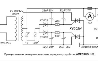
To assemble a battery charging device with your own hands, you will need :
- Transformer TH61-22, in which the windings are connected in series. It is characterized by an efficiency of at least 0.8 and a current not exceeding 6 A. A device with a power of 150 W is sufficient for this. The transformer on the secondary winding must produce a voltage of up to 20 V with a current of 8 A. If you cannot find a ready-made device with the necessary parameters, you can use any transformer of the required power, in which you can rewind the secondary winding with your own hands, which will allow you to obtain the necessary output current characteristics.
- MBGCh series capacitors operating with a voltage of at least 350 V and supporting alternating voltage.
- Diodes rated for a current of about 10 A.
- Device for changing voltage. An ammeter operating with direct current or an electromagnetic head similar to M24 is suitable for this.
Read also: We talk about autonomous power supply systems at home
Simple memory circuit
One of the most popular starting and charging devices is a device assembled on a capacitor circuit. It is characterized by a fairly high efficiency, does not emit heat during operation, has a stable current that does not depend on charge and supply fluctuations, and is protected from short circuits.
Step by step assembly
You can create one of the options for a starting charger with your own hands according to the following instructions:
- A suitable device circuit for charging the battery is selected (in this case, a capacitor circuit).
- A suitable case is selected in which a board with device parts and a transformer can be placed. This can be the case of a milliammeter, from which the contents except the pointer component are removed.
- The transformer is screwed onto an aluminum plate, which is fixed to the housing.
- A textolite plate is installed inside the case, with capacitors, relays, and other parts attached to it.
- The voltage regulator and terminal leads are attached to the housing.
- A massive aluminum radiator is mounted outside to cool the power diodes, as well as a fuse and a power supply plug.
- The voltmeter scale may not be suitable for the required measurements, and then a new one is made on a dense base and glued on top of the existing one.
- All parts are connected to each other according to the diagram.
- The wires with “crocodiles” running from the charger to the battery must be at least 1 mm in cross-section.
Efficiency mark
Most homemade car starting and chargers have a simple circuit, are quite reliable, are not very efficient, but they get the job done.
If desired, the efficiency of the device can be increased by choosing a more complex circuit, which will make it possible to operate in various modes, including automatic, as well as with protection functions against short circuits, overheating and battery overcharging.
Another option on video
Other circuit options and their assembly
There are many options for car chargers, the diagram, video instructions and assembly procedure of which are widely presented on the Internet.
The following devices are the most popular due to their simplicity and efficiency:
Read also: Review of voltage stabilizers Resanta 220V
Charger from the computer's power supply case . A power supply with a power exceeding 150 W is suitable, since to charge the battery, you need a current of 10% of the battery capacity. The following changes must be made to the design:
- Disconnect unnecessary pins (-5 and +5 V, -12 and +12 V);
- Replace resistor R1 with an interlinear one with a characteristic of 27 kOhm;
- The +12 V voltage is removed from the top terminal;
- A potentiometer-regulator is installed at the back and a power cable with cords and “crocodiles” is issued.
A battery charger made from a computer's power supply makes it impossible to overcharge or overheat the battery. If it is used only according to its intended purpose, an ampere and voltmeter need not be installed, and human intervention is not required during charging.
A similar option is shown in the video
Simple charging made from a 12V adapter . In this case, its circuit is not needed, but you need to take into account its output voltage must be equal to the battery voltage, otherwise it will not charge. “Crocodiles” are placed on the adapter wires, in which the polarity is marked with color or another method. The terminals are connected in series to the battery and the device is turned on.
The difficulty in choosing a charger from an adapter lies in the correct choice of power source. When using it, the battery may overheat, and then the process is interrupted for some time.
Similar option on video
Charging from a diode and an incandescent lamp . The device diagram includes the following elements:
- A diode that allows current to flow in only one direction. An alternative is a laptop power supply;
- Incandescent lamp, power up to 200 V. The larger it is, the faster the charging;
- Terminals, leads and plug.
Before assembling the device, it is advisable to watch a video that shows the features of connecting parts and operating the charger. So, with the correct setting, the lamp will glow in the channel floor. When the battery is fully charged, the light may not light up at all. The whole process takes about 10 hours, after which the device must be turned off so as not to cause overheating of the battery.
Read also: Selecting oil for an air compressor
One very simple option is shown in the video
Reverse polarity protection
A common problem with the failure of a starter-charger is its switching on with incorrect polarity .
To eliminate the problem of contact reversal, the device circuit must include a relay and a diode that will not allow current to flow in the wrong direction, and the wrong charge will not flow to the battery.
If the polarity is correct, the relay closes and charging begins. This circuit is relevant for any type of thyristor or transistor devices.
Setup and launch
With error-free assembly and suitable circuit elements, the device is immediately ready for use , you just need to set the voltage threshold with a variable resistor.
The device is adjusted during the charging process, but it is better to check and adjust the regulation and protection areas with your own hands in advance using a tester.
The device is started in the following order:
- Removing the car battery and cleaning it from dirt and acid residues.
- The plugs in the battery are removed and the electrolyte level is checked. If necessary, add water.
- The starter-charger regulator is set to the desired charging current reading, the contacts are connected to the battery observing polarity.
- The device turns on, and depending on the state of battery charge, the current is periodically adjusted until the battery is 100% charged.
If you have basic technical knowledge and the necessary parts, you can assemble a starting and charging device, which will definitely be useful to a car enthusiast, especially in winter.
In conclusion, another interesting device option
If you lack experience, you can always find a video on the Internet that describes in detail various chargers, their circuit and assembly process. Such a device will perform the same functions as a factory-produced one, but will cost much less.
Source: http://generatorexperts.ru/elektrogeneratory/samodelnoe-zaryadnoe-ustrojstvo-dlya-avtomobilnogo-akkumulyatora.html