VAZ 2114 dashboard pinout
The state of the most important automotive systems, which are responsible for road safety, travel speed, and the remaining travel time to the previously designated destination, can be seen on the dashboard if it is in good condition.
In addition, the dashboard also shows problems encountered along the way, gasoline consumption, the status of electrical equipment and much more.
All these indicators are irreplaceable on the road, and if you pay attention to the alarm signal in time, you can not only protect your car from possible breakdown, but also save your own life.
How the control panel works
The main symbols that are found on the dashboard of absolutely any car are:
- Speedometer.
- Fuel sensor.
- Tachometer.
- Sensors to indicate engine temperature.
The latter, by the way, has the shape of an arrow and is located on the panel on the left side. If you see that the needle of this sensor has exceeded 105 degrees, you should immediately park the car and let the engine cool completely before it boils.
The tachometer on the instrument panel is also presented in the form of an arrow located on a dial scale. Thanks to it, the driver is able to maintain engine speed in the range from 2 to 5.5 thousand, which is considered the norm for the VAZ-2114.
You should not allow the tachometer needle to enter the red zone, since fuel consumption will be significantly increased, as well as the load on the engine itself.
It’s hard to imagine a car’s dashboard without a speedometer. Thanks to its presence, the driver can monitor his speed limit, adhere to traffic rules and protect himself from possible unpleasant situations on the road. This device is the most important part of the panel, and therefore must work properly and show exclusively true data.
The fuel gauge is located on the right side of the dashboard and shows the approximate amount of fuel remaining in the vehicle's tank.
Thus, it becomes clear that thanks to the dashboard, the car driver can receive a huge amount of useful and necessary information. Namely:
- what is the speed of the vehicle;
- number of revolutions of the running engine;
- presence of gasoline in the tank;
- condition of some car parts, etc.
Pinout of the instrument panel VAZ-2114
To begin with, I would like to explain what pinout is. So, the latter is called a special diagram on which each individual part of the dashboard is designated by numbers. But for many people, describing this pattern in words is much easier to understand.
Therefore, we will try to do it this way.
There are 26 contacts on the VAZ-2114 instrument panel, each of which is responsible for the operation of the indicators of this panel. If a plus is supplied to the panel, then each contact displays information about the state in which the car is currently located.
In addition, special indicators and signal sensors are installed on the instrument panel, and the panel itself is controlled by a special electronic unit. Having disassembled the instrument panel, you can see that there are two pads inside it: red and white.
And all inputs, outputs and fuses are connected to the plug. If the sensors fail, they will need to be replaced. It is also better to replace damaged or oxidized wires. Indicator lights, like any other, sometimes burn out. Undoubtedly, they need to be replaced with whole ones.
Along with them, the lamp sensor often burns out.
Dismantling the control panel on a VAZ-2114
In order to carry out the above manipulations, it is necessary to dismantle the panel. You can do this in the following way:
- The center console is attached to three self-tapping screws, which can be easily unscrewed using a Phillips screwdriver.
- Move the protrusion away from the bracket and remove the cover.
- Unscrew the five screws located to the right of the console and remove the screen located there.
- Disconnect the negative terminal from the battery. If the car has a radio, it must also be removed.
- The wires that lead to the cigarette lighter are disconnected, and along with them the cartridge is disconnected.
- The handle is removed from the levers. This is done using a flat-head screwdriver.
- The handle is removed by moving it towards you, which is done not far from the fan and heater.
- There are two screws above and below the panel that need to be unscrewed.
- Behind the panel you will find another self-tapping screw that needs to be manipulated in a similar way.
- The trim is attached to the panel using two more screws. I think it’s not difficult to guess what to do with them.
- Next, the pads are disconnected from the wires and the harness. But before you do that, it's best to mark which wire goes where. This action is necessary to ensure that there is no confusion when installing the panel.
- Get rid of all remaining mounting bolts.
- The bottom bracket is attached using two self-tapping screws, which should also be unscrewed.
- Get rid of the self-tapping screw that secures the LED and heating unit.
- Remove all existing lamp sockets.
- Remove the decorative insert.
- Using a 21mm wrench, unscrew all visible nuts.
- Remove the hydrocorrector lamp.
- On the left side of the cross member there are self-tapping screws, unscrewing which will be the final step in dismantling the dashboard.
Reassembling the panel is done in the reverse order.
In this article, you learned why the dashboard pinout on a VAZ-2114 is needed, as well as how to properly dismantle it if necessary. We hope you found the article useful.
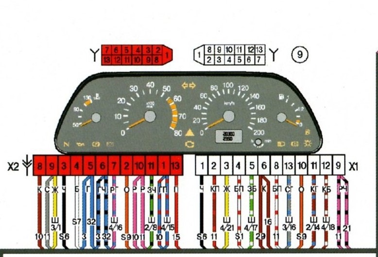
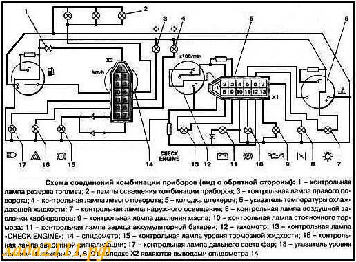
Diagram and pinout of the instrument panel (dashboard) VAZ-2113, 2114 and 2115
Designations of icons on the instrument panel (dashboard) of VAZ-2113, 2114 and 2115
1 – coolant temperature indicator.
2 – tachometer; 3 – control lamp for left direction indicators; 4 – control lamp for right direction indicators; 5 – speedometer; 6 – fuel level indicator; 7 – fuel reserve warning lamp; 8 – side light indicator lamp; 9 – warning lamp of the service brake system; 10 – control lamp for high beam headlights; 11 – reset button; 12 – mileage indicator; 13 – warning lamp for turning on the hazard warning lights; 14 – “check engine” warning lamp; 15 – time and temperature indicator; 16 – battery charge indicator lamp or battery lamp; 17 – parking brake warning lamp; 18 – oil pressure warning lamp;
19 – reserve;
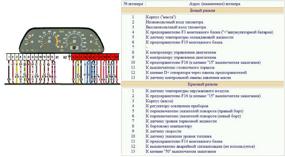
Pinout of the instrument panel (dashboard) VAZ-2113, 2114 and 2115
Pinout of instrument panel pads (instrument) VAZ-2113, 2114 and 2115
White block (X1)
Red block (X2)
Housing (weight) - black
To ambient temperature sensor - cyan-magenta
Tachometer (low voltage input from ECU) - brown/purple
Fuse F16 (to terminal 15 of the ignition switch) - orange
Tachometer (high voltage input from coil) - yellow
Housing (weight) - black
To fuse F3 of the mounting block (+battery) - white-purple
Instrument lighting control - white
Coolant temperature sensor. - green-white
Turn signal RIGHT - blue
To fuse F10 of the mounting block - brown
Turn signal LEFT - blue-black
Brake fluid level - pink-blue
Check Engine Light to ECU Controller - White-Purple
To the trip computer - brown
To the ECU controller - pink and black
Speed sensor - gray and yellow
To the fuel gauge sensor - orange
To the fuel gauge sensor - pink
To the parking brake switch - brown-blue
Fuse F14 of the mounting block - green-black
Alternator terminal "D" through fuse panel - brown and white
Hazard switch
Oil pressure sensor - blue
To terminal “50” of the ignition switch - purple
Date added: 07/14/2014
Source: http://ladafakt.ru/raspinovka-pribornoj-paneli-vaz-2114.html
Pinout, tuning, lighting and removal of the VAZ-2114 instrument panel
The VAZ dashboard has an electronic combination, as well as conveniently located backlighting. The lamps are illuminated from the inside, which is a feature of the 14th Lada.
Thanks to the instrument panel, the driver knows all the information he needs, what is the reserve and consumption of gasoline, mileage, etc. The panel should be easy to operate with a clear overview of the icons, scale, gauge and indicators.
What is the state of the automobile systems responsible for road safety, driving speed, the rest of the way to the intended object, rational engine operation and gasoline consumption, the operation of the suspension and electrical equipment - all this should be reflected on the control panel.
Signal lamps and equipment control devices must be required on the panel. There are a total of 19 symbols on the panel.
Control panel design
The main symbols include the fuel level, speedometer, tachometer, and sensors for cooling the liquid. The temperature sensor is indicated by an arrow on the left side of the panel.
If the sensor needle is in the zone from 105 to 130 degrees, you should immediately stop the car and wait until the engine cools down, otherwise the engine will simply boil. The tachometer is presented in the form of a dial scale on the instrument panel.
Engine speeds from 2 to 5.5 thousand per minute are considered the norm. If the needle falls into the red zone, fuel consumption may increase sharply, and the load on engine parts will become greater. The panel must have a speedometer.
With its help, the driver controls the speed, which directly affects road safety. The speedometer is an important part and should show clear data.
The sensor is located in the form of an arrow, which shows the fuel level in the car tank and is usually located on the right side of the device. Although it will not measure exact data about gasoline, you can find out the approximate fuel remaining at any time.
The panel design is quite simple, and at the same time highly informative; removing it is not difficult.
Using the panel, you can get a lot of useful information, namely: - is the condition of the VAZ safe at the time of movement - what is the speed, revolutions, availability of gasoline - what is the condition of the car's spare parts - other information, date and time.
With the help of sensors and meters, the driver is aware of all the information about his car. The VAZ tidy is made of plastic, which gives it an aesthetic appearance; it does not creak at all, unlike the same nine.
The device is simple, easy to disassemble and assemble.
What is the cost of the instrument panel on a VAZ 2114
In the online store, the panel can be found within 10 - 12 thousand rubles.
A new device does not cost more than 15,000 rubles, and markets and stores always have it in stock. Naturally, a europanel will be 6–8 thousand more expensive.
VAZ 2114 instrument panel pinout
Electrical connection diagram for the instrument panel of the VAZ 2114 (Click on the picture to enlarge)
- — rear window heating switch;
- — rear fog lamp switch;
- — switch for headlights and direction indicators;
- — mounting block;
- — windshield wiper switch;
- — fog light switch;
- — display unit of the on-board control system;
- — block of the instrument panel harness to the additional harness;
- — instrument cluster;
- — instrument panel harness connector to the on-board computer harness;
- — block of the instrument panel harness to the ignition system harness;
- — block of the instrument panel harness to the side door harness;
- — fuse 16 A;
- — fuse 16 A;
- — ignition switch;
- — lighting switch;
- — heater electric motor;
- — additional resistance of the heater electric motor;
- — ignition switch unloading relay;
- — Rear fog lights relay;
- - starter relay;
- — socket for connecting a portable lamp;
- - cigarette lighter;
- — block of the instrument panel harness to the wiring harness of the glove box lighting lamp;
- — illuminator;
- — illuminator;
- — illuminator;
- — heater switch;
- — instrument lighting regulator with rheostat;
- — brake signal switch;
- - horn switch;
- - hazard warning switch;
- — backlight lamp for heater control panel;
- — fuse 16 A;
- — seat heating relay;
The panel pinout is a diagram, but the diagram described in words seems easier for many. The contacts located on the instrument panel, and there are only 26 of them, are responsible for the operation of the indicators on the panel itself.
If a plus is applied, then each of the contacts shows information and the state in which the car is currently located. The panel is equipped with sensors and signal indicators, and the panel is controlled using an electronic unit.
Inside the panel there are two pads - red and white. Fuses, inputs and outputs, controllers are connected to a specific plug. If the sensors fail, they need to be replaced.
You can check the serviceability of the wiring by disassembling the instrument panel. Oxidized or damaged wires must be replaced. Indicator lights may fail. Burnt out light bulbs must be replaced with new ones.
A faulty lamp sensor must also be replaced. The contact between the board and the lamp must be well connected, otherwise the ends of the contacts should be cleaned, bent, and if necessary, replace the lamp socket.
If the backlight stops working or the radio is faulty, the fuse must be replaced. Maybe the damage is not in the fuse, but in the wiring, which also requires replacement.
A short circuit in the fuse can also damage it.
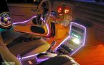
Tuning the dashboard of Lada 2114
To make their car distinctive, many motorists resort to tuning.
Although this is a troublesome task, it is worth it. Everyone strives to make the salon spectacular and cozy. The dashboard is a favorite place for tuning.
Backlight tuning
To make the panel devices look stylish and modern, they can be modernized. Let's look at how backlight tuning is done.
You can improve the appearance of a vehicle yourself, since the process is not at all complicated.
Everything you need for tuning:
- panel disassembly;
- removing the shield;
- tune the necessary parts;
- put in place.
The first step is to replace regular yellow light bulbs with bright LEDs. Chinese diodes are cheaper, but they will not last long. To ensure that the light comes directly from the diodes, heat shrink is put on them, and the arrows will be clearly visible even in the dark.
The diode wires are connected to the backlight from the machine stove. To change the color of the arrows, a red diode is placed under each arrow. The light from the arrows will acquire a rich, bright red color, which will noticeably update the panel.
Blue light bulbs are popular. The central panel is also subject to tuning, respect is guaranteed. The glow becomes soft and irritates the eyes when driving.
Europanel
To give a modern aesthetic look, you can install a europanel. The material of the panel is soft, rich, and less noisy. The original warning lamps and odometer make the panel modern and fashionable. It is equipped with many signal sensors. A special feature of the Europanel are sensor signals and airbags.
White-blue LEDs also look beautiful. Typically, up to 50 LEDs are needed for tuning. If the glow of the diodes is very bright, then you can try to adjust it. Some VAZ components have this capability.
You can also tint the instrument panel, which will also look great. Improving the panel offers ample opportunities for creativity among car enthusiasts and designers. As a tuning option, you can install a start button, which will give the interior a distinctive style and modernity.
By the way, if the modernization will be carried out with your own hands, in order to avoid problems with the traffic police, you need to write a statement about the planned changes in the design of the car and wait for permission from the traffic police. After making changes, you need to undergo a technical inspection, where appropriate changes will be made to the registration documents.
Instrument panel lighting
The role of illumination on the panel is performed by incandescent lamps located at the top of the panel. Even higher, there is a green filter. The standard backlight color can be changed to a beautiful LED color.
To do this, you will need three LEDs, cartridges for them, foil and tape. The green filter can be removed altogether, or replaced with a different color.
And if you put a white LED on top of the filter, the glow will become brighter and more beautiful. The service life of the battery will become noticeably longer if you replace incandescent lamps with diodes. Installing LEDs is easy.
Handle the arrows with care; they are very fragile. To dismantle the console, remove the arrows, glass, tab, and select the lamps. A total of 28 light bulbs are taken, 5 red, the rest - optional.
The top of the lamps must be filed with a file to ensure the correct direction of the light. Solder a resistor to each LED. To the red diodes - a resistance of 1.5 Ohms, to the rest - 1.1 Ohms.
A piece of plastic is taken, a form is cut to size for installing new lamps, holes are made on the form for installing new light bulbs.
The tracks with output to the power supply are soldered on the back side of the form. You can change the backlight of LCD screens in the same way. At the end of the work, connect the power and assemble the panel.
You can also change the backlighting of the buttons on the power windows.
If desired, the backlight can be installed in the gearshift lever handle, in the glove compartment.
To replace the backlight of the LCD screen, the plastic base is removed along with the bulb. The soldering method can replace the backlight of the indicators.
It is important to know that uninterrupted operation of LEDs is only possible if the connection polarity is observed. By the way, in this way, everything in the car will not rattle, which often happens in VAZs.
As an option, you can put a red LED under each arrow and put heat shrink on top of the shield so that the glow is direct. As a result, the backlight will become rich red. Illumination of instrument scales is done in the same way.
In fact, backlighting is important when driving at night, and being able to see your instrument panel clearly in the dark is very important.
Complete instructions for removing the control panel
To remove the device correctly, follow the instructions below:
- Using a Phillips screwdriver, remove the three screws that secure the center console;
- remove the cover, the protrusion located at the bottom, remove the protrusion from the bracket;
- Using a nozzle, unscrew the five screws located in the console on the right and remove the screen;
- Disconnect the terminal with the (-) sign from the battery. If there is a radio receiver, you need to remove it, remove the plug from the shield;
- Disconnect the wires coming from the cigarette lighter, remove the cartridge;
- Using a narrow screwdriver, remove the handle from the levers;
- pull the handle towards the heating and fan switch;
- unscrew the two screws above the panel and the two located under it using a screwdriver;
- unscrew the screw located behind the panel;
- Also unscrew the two self-tapping screws securing the cover;
- disconnect the harness and wire connectors. To avoid confusion when installing the panels, you should mark the order in which they are connected;
- unscrew the fastening bolts;
- unscrew the two self-tapping screws, those that secure the bottom bracket using an 8 key;
- unscrew the self-tapping screw securing the light guide and remove it;
- Also unscrew the screws securing the heating unit;
- remove lamp sockets;
- after removing the external parts, remove the decorative insert;
- unscrew all nuts with a 21 key;
- hydrocorrector, remove its lamp;
- Unscrew the screws that are attached to the cross member on the left.
Finally, the panel itself is removed. The panel is assembled accordingly in the reverse order.
It is important to remember the sequence of actions if you are performing this procedure for the first time. When disassembling and assembling you need to be extremely careful and attentive.
We also recommend watching
Source: http://natapku.ru/ustrojstvo/panel-priborov-vaz-2114.html
What does the VAZ 2114 instrument panel consist of?
The instrument panel of the VAZ 2114 is designed to inform the driver about the condition of the vehicle components.
Beginning motorists should find out more about the functions and capabilities of the panel, as it allows timely detection of some serious breakdowns.
In addition, some users may be interested in tuning the panel, so below are tips on what should be changed in the interior and how.
Main information devices
The instrument panels of the VAZ 2114 show information about the status of important operating components of the car. The main part is an information block with two round scales and several smaller indicators.
- The speedometer is the right round scale on the panel with marks from 0 to 200 km/h, which shows the speed of the car. The device sensor is located in the transmission assembly and is connected to the display in the cabin. Below the scale there is a window that displays the vehicle's mileage.
- The indicator to the right of the speedometer shows the level of gasoline in the tank. It has three main divisions - 1, ½ and 0. One - the tank is full, zero - empty. When the fuel is running low, the orange fuel icon lights up.
- The tachometer is the second large round scale, which is located on the left of the panel. Displays information about the crankshaft rotation speed - engine operation. Its norm is 3500-5500 rpm, everything beyond that is a critical value at which breakdowns of the engine unit occur. The indicator below the scale displays the air temperature around the engine.
- The small indicator to the left of the tachometer is the cooling fluid temperature sensor. Values from 50 to 130°C, where a value of 105°C and above indicates possible engine overheating.
Indicators
The VAZ 2114 injector dashboard indicators play an important role in informing the user about malfunctions. They help prevent errors in the system, so it is important to know which indicator means what. How does the panel work? If any problem occurs, the sensor immediately sends information to the panel, and the driver will see an orange signal light up.
- The first icon is an oil lamp, which indicates a drop in the oil level in the crankcase of the engine assembly. If there is not enough oil, this indicator will light up. An icon that looks like a fountain indicates that there is insufficient coolant. If it lights up, there is less than 1 liter in the tank.
- Dome with a key - if it lights up, it means there is not enough coolant in the expansion tank.
- The icon looks more like a belt buckle and indicates that the car doors are not completely closed.
- A light bulb crossed out with a cross indicates that the parking lights or brake lights are faulty. Most likely, one of the devices will need to be repaired.
- A circle with six dotted symbols is a graphical indication of a malfunction in the brake system. Most likely, the pads are worn out and need to be checked and replaced.
- An icon with a man and seat belts is an indicator indicating that the driver has not fastened his seat belt.
The earlier version of the 2114 instrument panel had some other symbols, such as emergency oil pressure, handbrake engaged, Chek Engine light, and several others that indicate minor operating errors, but which are no longer used.
Pinout
The VAZ 2114 instrument panel pinout shows the correct order of connecting the wires of measuring and information devices, in other words, this is the electronic circuit of the instrument panel.
You will need it if you want to make any changes to the standard panel configuration or carry out repairs and replacement of parts.
For each car model and specific dashboard, the diagram will be slightly different; for example, the diagram on the VAZ 2115 has significant differences from the 2114 model.
The circuit consists of 26 connections, which are made according to an electronic circuit. Usually the diagram should come with the car manual. It’s not a problem to get a description of her work now.
There are two pads inside the panel - one red and one white. The devices will be connected to them in a certain sequence.
There is nothing complicated in the pinout if the user has basic knowledge of the rules for connecting wires - plus to plus, minus to minus. If you have a diagram of the instrument panel on hand, you can start tuning individual devices or the entire set so that the instrument panel of the 2114 model becomes more visually pleasing.
Tuning options
The instrument panel of the 2114 looks rather dim, so the first option for tuning it may be to install a backlight. This is done quite simply:
- We replace dim lamps with small LED lamps. If you want the light from them to fall evenly, install heat shrink on the lighting elements.
- The wires for the new lamps are connected to the power supply of the stove. You should not use a lot of bright colors, but red and its shades are best for arrows. An excellent analogue would be the blue color of LEDs.
- The second illumination option can be a luminescent tape, which can be used to paste over the instrument panel of the 2114 VAZ. This will slightly update and improve the overall appearance of the interior. You can also replace the interior lamps with diode analogues.
In order for the instrument panel on the VAZ to have a clearer visual perception, the buttons should also be backlit.
Conclusion on the topic
Of course, her appearance leaves much to be desired, but this can be changed by adding a little visual effects. The last tuning option is to completely replace the panel with a European version. Everything you need is already installed, all you have to do is connect a few wires and turn on the new display system.
Source: https://korchim.ru/biblioteka/ehlektrika/panel-priborov-vaz-2114.html
Pinout of connectors for VAZ instrument panels of the tenth family
 Instrument cluster diagram:
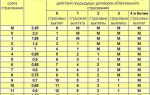
Connector pinout:
| White block (X1) | Red block (X2) | ||
| 1 | Housing (weight) | 1 | * External air temperature sensor |
| 2 | Tachometer (low voltage input from ECU) | 2 | Fuse F19 + 12V power supply |
| 3 | Tachometer (high voltage input from coil) | 3 | Housing (weight) |
| 4 | Const +12V from battery (via 6th fuse) | 4 | Instrument lighting switch |
| 5 | Coolant temperature sensor. | 5 | Turn signal RIGHT |
| 6 | Fuse F1 (side light) | 6 | Turn signal LEFT |
| 7 | Throttle valve (“choke”) | 7 | Brake fluid level |
| 8 | Check Engine Light | 8 | To the trip computer |
| 9 | Fuse F19 + 12V power supply | 9 | Speed sensor |
| 10 | Fuse F19 + 12V power supply | 10 | Terminal “T” fuel gauge |
| 11 | Parking brake, terminal “VK” | 11 | Fuse F3 (high beam) |
| 12 | Generator output “D” | 12 | Hazard switch |
| 13 | Oil pressure sensor | 13 | To terminal “50” of the ignition switch |
* – in relation to double-window panels VDO and Schetmash. An external ambient temperature sensor from VDO is installed. Mounts under the bumper. Not used on single-window versions. On panels with a mechanical odometer, this contact receives a signal from the “W” terminal of the fuel level sensor. Color coding for the wiring of various panels:
| Connecting wires to the VDO panel | |||||||
| White block | Red block | ||||||
| 1 – Black | 1 – Blue-red | ||||||
| 8 | White-red | 2 | Brown-red | 8 | Brown | 2 | Orange |
| 9 | 2 orange | 3 | Yellow | 9 | Grey | 3 | 2 black |
| 10 | 2 orange | 4 | Red-blue | 10 | Pink | 4 | White |
| 11 | 2 brown-blue | 5 | Green-white | 11 | 2 Green-black | 5 | Blue |
| 12 |
Brown-white |
6 | Yellow-black | 12 | Blue-white | 6 | Blue-black |
| 13 | Gray blue | 7 |
– |
13 | White | 7 | Pink blue |
| Connecting wires to the “Schetmash” panel, Kursk | |||||||
| White block | Red block | ||||||
| 1 – Black | 1- Blue-red | ||||||
| 8 | White-red | 2 | Brown-red | 8 | Brown | 2 | Orange |
| 9 | Blue | 3 | Yellow | 9 | Gray+yellow | 3 | Black |
| 10 | Orange | 4 | White-red | 10 | Pink | 4 | White |
| 11 | Brown blue | 5 | Green-white | 11 | Green-black | 5 | 2 blue |
| 12 | Brown-white | 6 | 2 Brown | 12 |
– |
6 | 2 blue-black |
| 13 | Gray blue | 7 |
– |
13 | Red | 7 | Pink blue |
| Connecting wires to the “AP” panel, Vladimir | |||||||
| White block | Red block | ||||||
| 1 – Black | 1- blue-red | ||||||
| 8 | White-red | 2 | Brown-red | 8 | Brown | 2 | Orange |
| 9 | 2 orange | 3 | Yellow | 9 | Grey | 3 | 2 Black |
| 10 | 2 orange | 4 | Red-blue | 10 | Pink | 4 | White |
| 11 | 2 brown-blue | 5 | Green-white | 11 | 2 Green-black | 5 | Blue |
| 12 | Brown-white | 6 | Yellow-black | 12 | Blue-white | 6 | Blue-black |
| 13 | Gray blue | 7 |
– |
13 | Red | 7 | Pink blue |
Scheme:
|
Connecting VDO on a Kalina car |
||
| 1 | Pink-white | To electric power steering |
| 2 | Blue and white | To the hazard warning indicator |
| 3 | Gray-blue | To emergency oil pressure sensor |
| 4 | Brown blue | To the parking brake switch |
| 5 | Yellow-blue | To the immobilizer control unit |
| 6 | Black | To the airbag control unit |
| 7 | Yellow | To the outside light switch |
| 8 | Blue | To the right turn signal switch |
| 9 | Blue with black | To left turn signal switch |
| 10 | White-blue | TO ECU |
| 11 | . | To brake pad wear sensor |
| 12 | . | To seat belt sensor |
| 13 | Black | To the traction control control unit |
| 14 | Red-blue | “RESET” key on the steering column switch |
| 15 | Pink-blue | To brake fluid level sensor |
| 16 | Black | To ABS |
| 17 | Green | To the high beam switch |
| 18 | White | To the instrument cluster light control |
| 19 | Brown | Panel weight |
| 20 | White-red | Terminal “30” |
| 21 | Orange | Terminal “15” |
| 22 | Yellow-red | To fuel flow sensor |
| 23 | Orange-white | MK key “forward” |
| 24 | White black | MK key “back” |
| 25 | Black and white | Outside temperature sensor (-) |
| 26 | Yellow-green | Outside temperature sensor (+) |
| 27 | Pink | Fuel level sensor |
| 28 | Grey | Speed sensor |
| 29 | Green-white | Coolant temperature sensor |
| 30 | Brown-red | Tachometer (low voltage) |
| 31 | . | Official. Panel diagnostics. |
| 32 | Brown-white | Terminal “L” of the generator relay regulator |
| Connecting the Itelma control panel with navigation |
|
| 1 | To electric power steering |
| 2 | MUTE |
| 3 | To oil pressure sensor |
| 4 | Parking brake switch |
| 5 | To the immobilizer control unit (electrical accessories) |
| 6 | To the airbag control unit |
| 7 | To the light control module (light on indicator) |
| 8 | Turn signal switch (right side) |
| 9 | Turn signal switch (left side) |
| 10 | To the engine control unit |
| 11 | AUDIO OUT – “Battery” |
| 12 | To the seat belt sensor |
| 13 | To ABS unit (EBD malfunction) |
| 14 | Steering column switch “Buttons” |
| 15 | Brake fluid level sensor |
| 16 | To ABS unit (ABS malfunction) |
| 17 | To the high beam switch |
| 18 | To the light control module (scale lighting regulator) |
| 19 | Frame |
| 20 | Terminal “30” battery |
| 21 | Terminal “15” of the ignition switch |
| 22 | To the control unit (fuel consumption signal) |
| 23 | To the steering column switch “UP” |
| 24 | To the steering column switch “DOWN” |
| 25 | To the radio “AUDIO OUT “+” |
| 26 | To outside temperature sensor |
| 27 | To fuel level sensor |
| 28 | To speed sensor |
| 29 | To coolant temperature sensor liquids |
| 30 | To control block engine (tachometer signal) |
| 31 | Service diagnostics |
| 32 | To terminal “L” of the generator relay regulator |
| Connecting the Itelma gearbox with navigation to a vehicle with CAN |
|
| 1 | To electric power steering |
| 2 | MUTE |
| 3 | Reserve |
| 4 | Parking brake switch |
| 5 | To the immobilizer control unit (electrical accessories) |
| 6 | Reserve |
| 7 | To the light control module (light on indicator) |
| 8 | Turn signal switch (right side) |
| 9 | Turn signal switch (left side) |
| 10 |
Reserve |
| 11 | AUDIO OUT – “Battery” |
| 12 | Reserve |
| 13 | Reserve |
| 14 | Steering column switch (Left, OK) |
| 15 | Brake fluid level sensor |
| 16 | Reserve |
| 17 | To the high beam switch |
| 18 | To the light control module (scale lighting regulator) |
| 19 | Frame |
| 20 | Terminal “30” battery |
| 21 | Terminal “15” of the ignition switch |
| 22 | Reserve |
| 23 | To the steering column switch (down, menu) |
| 24 | To the steering column switch (right, up) |
| 25 | To the radio “AUDIO OUT “+” |
| 26 | To outside temperature sensor |
| 27 | To fuel level sensor |
| 28 | CAN-L |
| 29 | CAN-H |
| 30 | Reserve |
| 31 | Service diagnostics |
| 32 | Reserve |
|
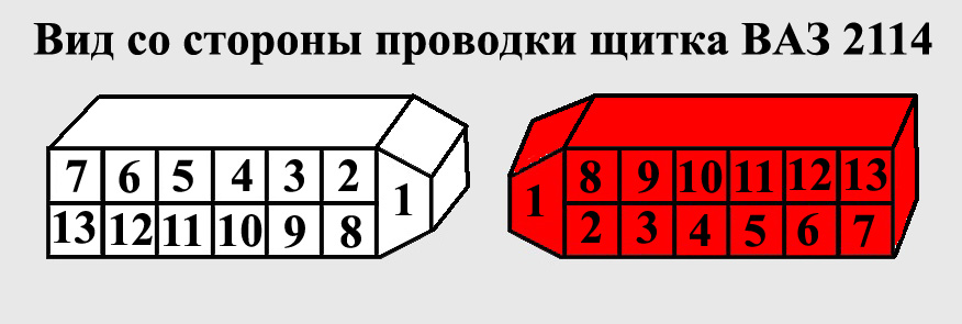
Connection to BI BSK VAZ 2114 (15) |
||
| 1 | Orange | To fuse F16 (Ignition switch terminal 15) |
| 2 | ——— | Not used |
| 3 | Black | Weight |
| 4 | White | To the lamp health monitoring relay |
| 5 | Gray (grey/goal) | To ignition switch microswitch |
| 6 | White black | To the interior lamp |
| 7 | Gray-black | To passenger door switches |
| 8 | Gray-white | To oil level sensor |
| 9 | Pink green | To coolant level sensor |
| 10 | Pink-white | To washer fluid level sensor |
| 11 | ——— | To seat belt sensor (not used) |
| 12 | Pink-orange | To brake pad sensors |
| 13 | Blue/white (2 pcs.) | To driver's door switch |
| Scheme | |||
| —- p u s t o —– | 1 | 17 | Green - black |
| Blue – White | 2 | 18 | White |
| Gray – Blue | 3 | 19 | Black |
| Brown – Blue | 4 | 20 | Red – Blue |
| —- p u s t o —– | 5 | 21 | Orange |
| —- p u s t o —– | 6 | 22 | Green |
| Yellow – Black | 7 | 23 | Orange – White |
| Blue | 8 | 24 | White black |
| Blue – Black | 9 | 25 | Black - red |
| White – Red | 10 | 26 | Pink - black |
| —- p u s t o —– | 11 | 27 | Pink |
| —- p u s t o —– | 12 | 28 | Grey |
| Black | 13 | 29 | Green – White |
| Red – Blue | 14 | 30 | Brown – Red |
| Pink – Blue | 15 | 31 |
—- p u s t o —– |
| Black | 16 | 32 | Brown – White |
|
What instrument cluster is on your car? |
Photo source:
Keywords:
Interesting site? Share with your friends
Source: http://xn--2111-43da1a8c.xn--p1ai/spravka/750-shema