The diagnostic system is just in case for me, and may be useful to someone else. — logbook of Toyota Corolla ae 110 made in Japan 1995 on DRIVE2
Diagnostic system used in Toyota cars.
These vehicles have diagnostic connectors called “DLC 1” and “DLC 2” (Data Link Connector). The first of them is a plastic rectangular box, usually located on the left side of the car, with “DIAGNOSTIC” written on it. Engine self-diagnosis is displayed through the “CHECK” light on the instrument panel.
But on some cars, instead of a “CHECK” light, there is a light with a picture of an engine, this is basically the same thing. Also keep in mind that some models of diesel cars use a spark plug glow lamp with a spiral design for self-diagnosis.
Malfunctions of an automatic transmission in self-diagnosis mode are usually indicated through the “OD” light (but it can also be a “POWER” or “AT CHECK” light), and malfunctions of the “ABS”, “TRC”, “SRS” systems through the corresponding indicator lights. The second diagnostic connector “DLC 2” is located under the bottom of the panel on the driver’s side.
It has a different configuration, since it is intended mainly for connecting special diagnostic equipment, but has the same pins as “DLC 1”. This connector, although inconveniently located, allows you to diagnose the car on the go.
On older (by year of development) diagnostic models, there are several yellow round connectors in the engine compartment closer to the battery, which are identical to the “DLC 1” connector (labeled “DIAGNOSTIC”). In this case there is no “DLC 1” connector. Toyota uses two types of codes for self-diagnosis of its cars.
The first is type 09. This is a two-digit code with the following parameters. Pulse width - 0.5 seconds. The pause between pulses is 0.5 seconds. The pause between tens and ones is 1.5 seconds. The pause between codes is 2.5 seconds. The pause between series of codes is 4.5 seconds. The second type of code used by Toyota is type 10.
This is a single-digit code, where the number of pulses is equal to the fault code. Its parameters are as follows. Pulse width - 0.5 seconds. The pause between pulses is 0.5 seconds. The pause between codes is 2.5 seconds. The pause between series of codes is 4.5 seconds.
In order to diagnose an engine or automatic transmission, you need to do the following. Open the hood of the car, and, finding a plastic box with the inscription “DIAGNOSTIC”, open its lid. On the back of this cap you will see pin markings.
Next, you need to take any piece of wire and plug it into the connectors so as to close the “TE1” and “E1” terminals. After that, get behind the wheel and, turning on the ignition and turning off the air conditioner and heater, watch the lights on the instrument panel. After turning on the ignition, the “CHECK” and “OD” lights will begin to blink.
If the lights blink continuously and frequently (flash - 0.5 sec., pause - 0.5 sec.) more than 11 times, this means that your car uses a two-digit code type 09 and no faults are recorded in the computer memory and, therefore, you can remove the jumper, start the engine and go about your business.
If the “CHECK” light blinks continuously at intervals of 4.5 seconds, then the car is using code type 10 and also no faults have been recorded in the computer memory.
If the light blinks like this: flash-pause-flash - long pause-flash - this means you have code 21 (two-digit) in your memory; if so: flash - long pause - flash - pause flash - then code 12 and so on.
If you are not sure that you have correctly identified the contacts that should be bridged, then we can recommend the following. The pin on the diagnostic chip “E1” is the housing.
If you take a “control” with a low-power light bulb, connect one wire to the car body, and touch all the terminals in a row in the diagnostic connector with a probe, then when you get to “TE1”, with the ignition on, the “CHECK” light will begin to blink.
In this way, you can find the diagnostic output of any car that has a “CHECK” light on the panel, without risking burning anything, since “control” is used, and even a low-power light bulb, for example from the instrument panel backlight, is used to trigger the self-diagnosis system , enough.
Fault codes for gasoline engines (Toyota)
Self-diagnosis codes are read by the number of flashes of the “CHECK ENGINE” indicator when the “TE1”-“E1” terminals of the DLC1 connector under the hood or “TC”-“CG” of the DLC3 connector under the dashboard are closed and the ignition is on.
12 - Crankshaft position sensor (P0335)13 - Crankshaft position sensor (P0335, P1335)14 - Ignition system, coil No. 1 (P1300) and No. 4 (P1315)15 - Ignition system, coil No. 2 (P1305) and No. 3 (P1310)16 - Automatic transmission control system18 - VVT-i system - phases (P1346)19 - Accelerator pedal position sensor (P1120)19 - Accelerator pedal position sensor (P1121)21 - Oxygen sensor (P0135)22 - Coolant temperature sensor (P0115)24 - Intake air temperature sensor (P0110)25 - Oxygen sensor - lean signal (P0171)27 - Oxygen sensor No. 231 - Absolute pressure sensor (P0105, P0106)34 - Turbocharging system35 - Turbo pressure sensor36 - CPS sensor (P1105)39 - VVT-i system (P1656)41 - Throttle position sensor (P0120, P0121)42 - Vehicle speed sensor (P0500)43 - Starter signal47 - Auxiliary throttle position sensor49 - Fuel pressure sensor (D-4) (P0190, P0191)51 - Switch status52 - Knock sensor (P0325)53 - Knock signal55 - Knock sensor No. 258 - SCV drive (D-4) (P1415, P1416, P1653)59 - VVT-i signal (P1349)71 - EGR system (P0401, P0403)78 - Injection pump (D-4)89 - ETCS drive (P1125, P1126, P1127, P1128, P1129, P1633)92 - Cold start injector (D-4) (P1210)97 - Injectors (D -4) (P1215)
98 — Vacuum sensor in the vacuum brake booster (C1200)
Fault codes for diesel engines (Toyota)
12 - Crankshaft position sensor13 - Speed sensor14 - Injection advance angle adjustment valve15 - Throttle valve servomotor17 - Control unit signal18 - Electromagnetic bypass valve19 - Accelerator pedal position sensor22 - Coolant temperature sensor24 - Intake air temperature sensor32 - Correction resistors35 - Pressure sensor boost39 - Fuel temperature sensor42 - Vehicle speed sensor
96 - EGR valve position sensor
Automatic transmission fault codes (Toyota)
Self-diagnosis codes are read by the number of flashes of the “O/D OFF” indicator when the terminals “TE1”-“E1” of the DLC1 connector under the hood or “TC”-“CG” of the DLC3 connector under the dashboard are closed and the ignition is turned on (in this case, turning on must be allowed overdrive — “O/D OFF” is off).
11 - Normal 37 - Automatic transmission input shaft speed sensor (P1705) 38 - Automatic transmission fluid temperature sensor 42 - Speed sensor (or output shaft speed sensor) (P0500) 44 - Speed sensor (or rear output shaft speed sensor) 46 - Solenoid accumulator pressure control (P1765)61 - Speed sensor (or front output shaft speed sensor)62 - Solenoid No. 1 (P0753)63 - Solenoid No. 2 (P07564 - Torque converter lockup clutch solenoid (P0773)67 - Automatic transmission input shaft speed sensor68 — Torque converter lockup clutch control solenoid
73 — Center differential lock clutch solenoid
SRS fault codes (Toyota)
Self-diagnosis codes are read similarly to others, by the number of flashes of the “SRS” indicator when the “TC”-“E1” terminals of the DLC1 connector under the hood or “TC”-“CG” of the DLC3 connector under the dashboard are closed and the ignition is on.
Codes should be erased when the ignition is turned off.
If the codes are stored, it is necessary to carry out the cleaning procedure: - connect two wires to the “TC” and “AB” terminals - turn on the ignition and wait at least 6 seconds - alternately, once a second, short the “TC” and “AB” terminals to ground ( pause between closures - less than 0.2 seconds) - after the third closure of the “TC” output, the indicator should flash at a high frequency - this means the codes are erased. Never erase the airbag system fault signal code without checking and finding out the meaning!
Ts
11 — Driver air protection igniter (short to ground)12 — Driver air protection igniter (short to power)13 — Driver air protection igniter (short circuit)14 — Driver air protection igniter (open circuit)15 — Front right SRS sensor (short or open) in the circuit)15 - Front right SRS sensor (short to ground or power)16 - Front left SRS sensor (short or open circuit)16 - Front left SRS sensor (short to ground or power)31 - Malfunction of the SRS control unit51 - Igniter Passenger CB (short to ground)52 - Passenger CB igniter (short to power)53 - Passenger CB igniter (short circuit)54 - Passenger CB igniter (open circuit)61 - Driver belt pretensioner igniter (short to ground)62 - Driver belt pretensioner igniter (short to power)63 - Driver belt pretensioner igniter (short circuit)64 - Driver belt pretensioner igniter (open circuit)71 - Passenger belt pretensioner igniter (short to ground)72 - Passenger belt pretensioner igniter (short circuit) for power supply)73 - Passenger belt pretensioner igniter (short circuit)
74 - Passenger belt pretensioner igniter (open circuit)
ABS fault codes (Toyota)
Reading codes (models with DLC1 connector)— Turn on the ignition.— Jumper the “TC” and “E1” terminals of the DLC1 connector.— Remove the jumper from the “WA” and “WB” terminals of the DLC1 connector.— After 4 seconds, read the code by the number of indicator flashes .—Remove the jumper from terminals “TC” and “E1”.
— Install a jumper on pins “WA” and “WB”.
Resetting codes (models with DLC1 connector)— Turn on the ignition.— Jumper the “TC” and “E1” terminals of the DLC1 connector (vehicle stationary).— Press the brake pedal eight or more times in an interval of three seconds.— The indicator should display the normal code ( blink 2 times per second).— Turn off the ignition.— Remove the jumper from the “TC” and “E1” terminals.
— Make sure the ABS indicator goes out.
Reading codes (models with DLC3 connector)—Jump the “TC” and “CG” terminals of the DLC3 connector.—Turn on the ignition.—After 4 seconds, read the code by the number of indicator flashes.
— Remove the jumper from the “TC” and “CG” terminals.
Resetting codes (models with DLC3 connector)— Jump the “TC” and “CG” terminals of the DLC3 connector.— Turn on the ignition.— Press the brake pedal eight or more times in an interval of three seconds.— The indicator should display the normal code (flashing 2 times per give me a sec).
— Remove the jumper from the “TC” and “CG” terminals.
11 Open circuit in the solenoid valve relay12 Short circuit in the solenoid valve relay circuit13 Open circuit in the electric pump relay circuit14 Short circuit in the electric pump relay circuit15 Short circuit in the circuit or open circuit TRAC solenoid reley21 Open circuit or short circuit in the front right wheel solenoid valve22 Open or short circuit in the solenoid valve of the front left wheel23 Open circuit or short circuit in the e/m valve of the rear right (left) wheel24 Open circuit or short circuit in the e/m valve of the rear left (right) wheel31 Malfunction of the front right wheel speed sensor32 Malfunction of the frequency sensor rotation of the front left wheel33 Malfunction of the rear right wheel speed sensor34 Malfunction of the rear left wheel speed sensor35 Open circuit in the front left/rear right wheel speed sensor36 Open circuit in the front right/rear left wheel speed sensor37 Faulty rear axle hubs41 Battery voltage is too high or too low43 Malfunction in the deceleration sensor circuit44 Open or short circuit in the deceleration sensor circuit49 Open in the brake light switch circuit51 Short circuit or open circuit in the electric pump power supply circuit52 The hydraulic control unit pump motor is blocked71 Low signal level from the front right wheel speed sensor72 Low signal level from the speed sensor front left wheel73 Low signal level from the rear right wheel speed sensor74 Low signal level from the rear left wheel speed sensor75 Incorrect signal change from the front right wheel speed sensor76 Incorrect signal change from the front left wheel speed sensor77 Incorrect signal change from the front left wheel speed sensor rear right wheel78 Incorrect change in signal from the rear left wheel speed sensor
79 Deceleration sensor fault
4WS system fault codes (Toyota)
Self-diagnosis codes are read by the number of flashes of the “4WS” indicator when the “TC”-“E1” terminals of the DLC1 connector under the hood are closed and the ignition is on
11 Electronic control unit 4WS12 Malfunction of the main electric motor of the rear steering gear13 Malfunction of the steering gear control drive21 Short circuit in the main electric motor system22 Open circuit in the main electric motor system23 Blocking of the main electric motor24 Malfunction of the main electric motor31 Open circuit in the reverse motor system32 Malfunction of the reverse motor41 Malfunction of the sensor left front wheel speed42 4WS system sensor malfunction
43 Incorrect operation of the 4WS system sensor
Source: https://www.drive2.ru/l/288230376152891770/
How to start Toyota self-diagnosis: step-by-step instructions. Self-diagnosis of Toyota automatic transmission
A car, as you know, is a means of transportation, but not a luxury item. But the cost of some diagnostic and repair operations casts doubt on this. In many ways, this also applies to Japanese cars that are popular among us.
So knowing how Toyota’s self-diagnosis starts, for example, can save you a lot of money.
There is nothing particularly difficult about this operation, you just need to be more careful and follow the instructions exactly.
So how to do a self-diagnosis? Toyota is a fairly new car (assuming that yours is not a rarity), and therefore it has quite a lot of electronic circuits that greatly facilitate this task.
In principle, any more or less modern car has a special engine self-diagnosis unit.
How does this mechanism work? Quite simple: electronics constantly monitors the performance of devices, comparing them with the reference values set by the manufacturer.
If something is wrong, a diagnostic program is activated, which specifically determines what exactly has gone wrong. Roughly speaking, this is how Toyota’s self-diagnosis works.
Only when all elements are in order will the bypass program be removed and the engine will begin to operate normally. Note that many are familiar with the illuminated inscription “CHECK” or a separate pictogram with an image of the engine, which indicate a malfunction. If the fault has been repaired, the image or icon goes out.
In general, this is self-diagnosis. Toyota in this regard is a very “friendly” car, since everything is immediately visible on the dashboard (in most cases), and the Japanese themselves took care of the availability of normal, detailed manuals and recommendations that describe all possible error codes, which makes life much easier for service workers and ordinary motorists.
How is this operation useful?
It is important to remember that data about an error that occurs must be entered into the memory of the on-board computer.
If its power was not interrupted (the battery was not removed, for example), this data can be read from the instrument panel (Toyota) or pulled out from the computer itself (Nissan).
In case of some malfunctions, the engine will immediately stall, but in some cases, when the malfunction prevents the operation of the machine, the error code is simply recorded in the internal memory of the computer.
This is very convenient, since later you will be able to find out all the details about the condition of your car. Actually, this is what self-diagnosis is good for. Toyota, therefore, compares favorably with other foreign cars in that you can save a lot on finding out the reasons why various problems occur.
In addition, this way you can find out the reasons why the car behaves abnormally from time to time. For example, you stopped due to a stalled engine in the middle of the road.
We turned the key in the ignition a couple of times - the engine started up smoothly and the car drove on. What was it? You definitely won’t know anything by eye, but if you look at the contents of the on-board computer’s memory, everything will become clear.
How does Toyota self-diagnosis start? Let's find out!
Start of diagnostics
Under the hood of the Toyota there is a special connector for diagnostics. It looks like a plastic box with DIAGNOSTIC written on it. You need to open its cover to see detailed markings of all pins on its reverse side.
After this, take any suitable piece of wire, which closes the “TE1” and “E1” connectors. Get behind the wheel of the car, turn on the ignition (be sure to turn off the air conditioning and heater), and then carefully monitor the “CHECK” lamp.
So, immediately after turning on the ignition, it should start blinking. If the lamp blinks continuously two or more times, then the computer memory is empty. You remove the jumper, close the diagnostic unit and go about your business further.
Worth knowing
Modern diagnostic units divide faults into two types: light and heavy, and in the first case they do not clog the memory of the on-board computer with error codes. So, if a simple malfunction disappears for some reason, then no records will remain about it.
It often happens that after driving on a bad, dirty road, “Jackie Chan” begins to signal a malfunction of the ABS system. The on-board computer will immediately turn it off.
But as soon as you wash the car properly after such a trip, the contacts will be cleaned and everything will return to normal without any repairs.
On which model does self-diagnosis most often end this way? "Toyota Corolla" of some series is the most striking example; such cars are completely unsuitable for driving on domestic roads.
Some error codes
Here's an example: a flash/pause, then a flash again, followed by a long pause and a regular flash, indicates error #21.
Another example: if after blinking there is a long pause, then blinking again and a pause, followed by a flash again, then this is error No. 12. Note that each Toyota engine has its own table of error codes.
But here it should be remembered that most motors in this regard are practically no different from each other, since many models simply do not provide some signals.
https://www.youtube.com/watch?v=DODq3guGB3A
In addition, in most cases they have different test standards: on one model the device can produce 0.45 volts, and on another – 0.5. We say all this so that you clearly understand: there are no fundamental differences in launching diagnostics, only the codes and reference values programmed at the factory differ.
The simplest table of fault codes is observed on old cars of the Japanese company.
If the car is working properly, then it simply blinks the light, and the interval between flashes is three seconds.
All faults are identified by only ten codes, so in this case self-diagnosis is extremely easy. The Toyota Corolla of the first families has just such a simplified system.
It is important to remember one simple rule: all engines of the Japanese concern are initially equipped with almost identical diagnostic programs. However, due to design differences that can occur even within the same family of the same Corolla, the signals will be completely different.
It is completely pointless to present them on the pages of this article, since this data should be in the operating manual of your machine itself. We strongly do not recommend using data from other models, since with this approach you may completely incorrectly diagnose the problem that has arisen in your car.
Differences in diagnostic blocks
On old Toyota cars there is no diagnostic unit, but there is a freely dangling “chip” with two contacts, protected by a plastic cap.
Actually, its outputs are similar to the “E1” and “TE1” connectors of new machines.
If there is nothing at all, then you can take a 12V lamp and two wires: one of them is grounded against the case, and with the second you should touch all “suspicious” connectors. Don't worry, you won't burn anything.
When you do find “TE1”, the lamp on the dashboard will immediately go out, and the on-board computer will begin to issue a fault code. Please note that when connecting the “E1” and “TE1” pins, not only the EFI diagnostics will be launched, but also a check of some third-party units.
Clearing memory from previous readings
As a rule, to do this, you need to pull out the HAZ-HORN fuse, and in other models - STOP (see your vehicle's owner's manual). Sometimes there is an EFI option.
However, everything can be done simpler: disconnect the negative terminal of the battery for half a minute, after which the memory will be reset to zero with a guarantee. But this will also erase the memory in the air conditioner and clock.
And also, if your car is 1998 or newer, such a harsh cleaning can cause problems with the operation of many systems, and all this can last up to several days.
This is explained simply: modern cars can adapt to a specific driving style, and the data is also stored in the memory of the on-board computer. However, this phenomenon also has a purely positive side.
Many of us buy a car after one or two owners, and their driving technique was not always satisfactory. Such a car can consume a lot of gasoline and react inadequately to the gas pedal.
In a word, she behaves badly and is clearly “asking” for a trip to the service center.
But before that, you may well try to reset your memory. As practice shows, this is often quite sufficient. In this case, you will not only save your money, but also gain important experience. But how to do a self-diagnosis? Toyota, as we have already said, does not present any special surprises in this regard, so nothing particularly difficult awaits you.
General procedure for diagnosing ABS and TRC
This is done in the following order:
- Turn on the ignition without starting the car engine. If there are differential locks, they need to be disabled, otherwise the self-diagnosis of the Toyota engine simply will not start due to software restrictions.
- Find the DLC 1 diagnostic unit (as we said, it is located under the hood), then, according to the “recipe” given above, insert a wire or wire jumper there. Note that the MR-2 model does not have the connectors we require in DLC 1. In this case, look for a dangling “medallion” with connectors that will hang near the engine. The body should say ABS.
- The ABS lamp will begin to blink, using its signals to determine a specific malfunction.
- After this, you can clear the computer's memory. You need to turn on the ignition, turn off the differential locks (if any), and then quickly press the brake pedal, and the interval between presses should not exceed three seconds. When the memory is completely cleared, the diagnostic lamp will begin to blink at intervals of 0.5 seconds between blinks.
In general, this is how Toyota ABS self-diagnosis is performed. The jumper with DLC 1 is removed, after which the standard part is installed in place. And in the case of ABS, the block is returned to its original state.
Box diagnostics
All of the above related mainly to taking readings from the engine. But what about self-diagnosis of Toyota automatic transmission? In general, there are no special differences (except for error codes, of course):
- Turn on the ignition, but do not start the car. In this case, the automatic transmission lamp should light up immediately and go out after three seconds. If this is not observed, then you will have to carefully check all the fuses, as well as the physical integrity of the lamp itself and the wires.
- Turn off the ignition. On the same DLC 1 connector, you need to connect the more than once mentioned “E1” and “TC” pins. Apply the handbrake, and immediately after that start the engine. Now the automatic transmission indicator should blink four times per second.
- Start moving in a straight line: you have to accelerate to at least 80 km/h. If the indicator continues to flicker at the same frequency, then everything is fine with the speed sensors. Otherwise, the check will have to be continued.
- Stop the car. After this, you need to remove the jumper between “TS” and “E1” and install it between “E1” and “TS”. Reading the codes. If there are more than two codes, then there will be an interval of 2.5 seconds between them.
- Clear the memory again using the method described above.
This is how self-diagnosis of a Toyota automatic transmission is performed. In some car models, it can be difficult to find the EFI unit. Typically, it is located under the front passenger seat or on the left pillar of the body.
In its metal case there is a clearly visible hole through which you can easily see two LEDs: red and green, with the help of which error codes are displayed.
In this case, the red LED produces tens of units, and the green LED – units.
In addition, there is also a connector for a screwdriver, with which you can select the test mode. Before starting the test, you need to make sure that this knob is turned clockwise all the way.
Other diagnostic schemes
There are two more schemes used on some car models of this company (in particular, this characterizes the self-diagnosis of the Toyota Mark 2). As a rule, they are used on early production machines. This operation should be carried out in this order:
- Turn on the ignition. After this, make sure that both diodes light up: if this does not happen, you will have to look for broken wires or other faults.
- Using a screwdriver, move the handle to the right until it stops.
- The following codes should be displayed in order: 23, 24 and 31. However, other errors may appear. If this happens, we advise you to write them down.
As we have already said, the red LED is a ten, the green LED is a one. For example, “23” will look like this: first the green light will blink twice, and then the red light will blink three times.
Important! If the machine is working properly, then after the three above codes appear there will be a long pause, and then the same signals again. And this will continue indefinitely.
In particular, this characterizes the Toyota Carina, the self-diagnosis of which, due to such cyclicality, is perceived inadequately by some mechanics, since they see errors in repeating signals.
If everything is OK, press and release the accelerator pedal. Signals 24 and 31 should remain. If any Toyota self-diagnosis errors appear, you need to write them down.
After that, start the car. Only signal 31 may remain, but 24 and 31 flash more often (in particular, this is how the Toyota Camry self-diagnosis is performed).
As in the previous case, write down additional codes (if they appear).
Turn the air conditioning system on and off again. After this, signals 44 and 24 (or one 44) should appear. Write down other commands (if any) and turn off the engine. After that, erase your memory.
To do this, you need to turn off the ignition and turn the knob with a screwdriver one by one to each extreme position (starting from the left, of course), holding it in each case for at least two seconds.
Remember that removing the battery does not always help, since some old units can “keep” the readings throughout the day.
Second diagnostic scheme
In the second case, a five-mode scheme is used, which can sometimes be found in some new cars. There are all the same LEDs and a handle, but you should work with them a little differently. Toyota Avensis is distinguished by this approach. Self-diagnosis of this vehicle is performed in the following order:
- As in the previous case, make sure that the handle is turned to the right all the way.
- Then turn on the ignition without starting the engine.
- The mode selector also needs to be turned all the way clockwise.
After this, in the normal state, both diodes light up briefly, followed by a long pause. Then the selector turns to the left, after which you can turn on the first mode. If you do not do this, there will again be a short flash and a pause, after which the second mode can be activated. This way you can get to the fifth diagnostic option.
Decoding modes
Regardless of the selected mode, the on-board computer can display all the error codes that are in its memory. If you do not stop it, then after a long pause the output will start from the beginning (in particular, this is how the Toyota Crown self-diagnosis is carried out). So, here is a description of all five possible options:
- checking the serviceability of the entire exhaust system;
- analysis of the state of the fuel mixture;
- self-diagnosis with a long list of possible errors;
- checking the starter, idle speed, etc.;
- diagnostics of a specific car breakdown.
This is approximately how Toyota self-diagnosis is performed. As you can see, there is nothing supernatural in such a test. The main difficulty is to correctly and timely detect all the moves issued by the system and then interpret them, using the most detailed operating instructions for your car.
Source: http://fb.ru/article/176725/kak-zapuskaetsya-samodiagnostika-toyotyi-poshagovaya-instruktsiya-samodiagnostika-akpp-toyotyi
Resetting Toyota errors – Autognostics
The “check engine” indicator tells the Toyota Corolla owner to check the power unit as soon as possible.
Previously, this flickering icon indicated a problem with the carburetor, but for a car with an on-board computer, it is a clear signal of malfunctions in other areas of the car: insufficient mixture in the engine, ignition state, etc.
The breakdown can be either critical or minor. Only Toyota diagnostics will give a complete picture. Let's look at the common reasons for a check to light up and what to do next.
- Why is the check engine light on and what should I do?
- How to diagnose an engine? 2.1. First of all 2.2. Types of error codes 2.3. Diagnostics
- Engine fault codes and methods for erasing them
Why is the check engine light on and what should I do?
Diagnostics by flickering of the check-engine icon and diagnostics of the car by computer
There are many reasons for the error to appear. The exact cause is determined by calculating the number of blinks, then you find the error code that corresponds to the specific problem (the list of codes will be given in the last section). If it is difficult for you to do such manipulations on your own, then undergo diagnostics at a service station.
How to diagnose an engine?
Toyota Corolla self-diagnosis will allow you to figure out the source of problems in your car. Let's figure out where to start, what the error codes are and how to carry out diagnostics without special instruments and tools right in the garage.
First thing
All Toyota models older than 1988 are equipped with a multi-pin connector for diagnostics, which is located under the hood near the battery or on the left side of the car (along the way). The connectors are called DLC-1 and DLC-2. Option with index 1 is a plastic box, which is often marked “Diagnostic”.
In this case, error codes are displayed directly through the “check” icon, located in a visible place for the driver. If you have a restyled or modern model of Toyota Corolla, then the light bulb is in the form of an engine, but it is the same thing. The previous information concerned owners of gasoline cars, because...
for diesel versions, instead of a separate light bulb, a candle incandescent light bulb is used: a picture in the form of a spiral.
After carrying out diagnostics on your own, errors in the event of an automatic transmission malfunction are displayed through the “AT Check”, “Power” or “OD” lamps. Failures in other systems, for example, TRS or SRS and ABS, are displayed on the corresponding lamps.
The second diagnostic connector DLC-2 is located next to the driver (the lower part of the panel near the driver's seat), which is convenient for diagnosing the car on the go. The purpose of this output is more professional, but it has similar outputs as the DLC-1.
Types of error codes
The manufacturer Toyota uses two types of codes: two-digit and single-digit codes. The main parameters of the codes are listed in the table below.
Diagnostics
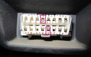
To diagnose a faulty unit, open the hood of the Toyota Corolla and find the diagnostic box called “DIAGNOSTIC”, which was mentioned earlier. On the back of the cover there is an output marking. The next important step is to close the two values “TE1” and “E1” (they are highlighted in the figure).
When both values are in the closed position, sit behind the wheel, be sure to turn on the heater, air conditioning, etc., and then turn on the ignition. When the error button flashes (“Check” or “OD”), pay attention to the nature of the lighting.
- If the check blinks more than 11 times continuously with an interval of 0.5 seconds, then your Toyota Corolla uses a two-digit code, such as 09. This option means that there are no recorded errors in the computer memory and you can safely remove the jumpers, start the car and go where you planned .
- When the error lamp flickers at intervals of 4.5 seconds, then your car is using type 10 codes, but the vehicle does not require serious repairs.
- If the “check-engine” blinks differently, for example: flickering - pause - flickering - long pause - flickering, then the error code is already in the memory of the on-board computer and its value is 21. Or this example of a check blinking: flickering - long pause - flickering - pause - flickering - this is error code number 12.
Each code indicates a specific error for cars with diesel or gasoline engines. Error codes and reset methods will be given in the last section, and now we continue to talk about diagnostics.
To make sure that the contacts are closed correctly, for example, “E1”. Take a low-power light bulb and connect one wire to the Toyota body, with the other end of the wire touch each wire in the connector in turn. When you find the “TE1” connector, the light on the dashboard will blink.
Another way to read error data is to use the interior console under the driver's seat. To start self-diagnosis, close other contacts in the places shown in Fig. below.
Engine fault codes and methods for erasing them
Fault codes for gasoline engines (Toyota)
12 - Crankshaft position sensor (P0335) 13 - Crankshaft position sensor (P0335, P1335) 14 - Ignition system, coil No. 1 (P1300) and No. 4 (P1315) 15 - Ignition system, coil No. 2 (P1305) and No. 3 (P1310) 16 - Automatic transmission control system 18 - VVT-i system - phases (P1346) 19 - Accelerator pedal position sensor (P1120) 19 - Accelerator pedal position sensor (P1121) 21 - Oxygen sensor (P0135) 22 - Coolant temperature sensor fluid (P0115) 24 - Intake air temperature sensor (P0110) 25 - Oxygen sensor - lean signal (P0171) 27 - Oxygen sensor No. 2 31 - Absolute pressure sensor (P0105, P0106) 34 - Turbocharging system 35 - Turbo pressure sensor 36 - CPS sensor (P1105) 39 - VVT-i system (P1656) 41 - Throttle position sensor (P0120, P0121) 42 - Vehicle speed sensor (P0500) 43 - Starter signal 47 - Additional throttle position sensor 49 - Pressure sensor fuel (D-4) (P0190, P0191) 51 - Switch status 52 - Knock sensor (P0325) 53 - Knock signal 55 - Knock sensor No. 2 58 - SCV actuator (D-4) (P1415, P1416, P1653) 59 - VVT-i signal (P1349) 71 - EGR system (P0401, P0403) 78 - Injection pump (D-4) 89 - ETCS drive (P1125, P1126, P1127, P1128, P1129, P1633) 92 - Cold start injector (D-4 ) (P1210) 97 - Injectors (D-4) (P1215)
Fault codes for diesel engines (Toyota)
12 — Crankshaft position sensor 13 — Speed sensor 14 — Injection advance angle adjustment valve 15 — Throttle valve servo 17 — Control unit signal 18 — Electromagnetic bypass valve 19 — Accelerator pedal position sensor 22 — Coolant temperature sensor 24 — Air temperature sensor inlet 32 — Correction resistors 35 — Boost pressure sensor 39 — Fuel temperature sensor 42 — Vehicle speed sensor 96 — EGR valve position sensor
Automatic transmission fault codes (Toyota)
Self-diagnosis codes are read by the number of flashes of the “O/D OFF” indicator when the terminals “TE1”-“E1” of the DLC1 connector under the hood or “TC”-“CG” of the DLC3 connector under the dashboard are closed and the ignition is turned on (in this case, turning on must be allowed overdrive — “O/D OFF” is off).
11 - Normal 37 - Automatic transmission input shaft speed sensor (P1705) 38 - Automatic transmission fluid temperature sensor 42 - Speed sensor (or output shaft speed sensor) (P0500) 44 - Speed sensor (or rear output shaft speed sensor) 46 — Accumulator pressure control solenoid (P1765) 61 — Speed sensor (or front output shaft speed sensor) 62 — Solenoid No. 1 (P0753) 63 — Solenoid No. 2 (P0758) 64 — Torque converter lock-up clutch solenoid (P0773) 67 — Frequency sensor rotation of the automatic transmission input shaft 68 — Torque converter lockup clutch control solenoid 73 — Center differential lockup clutch solenoid
ABS fault codes (Toyota)
Reading codes (models with DLC1 connector) - Turn on the ignition. — Jumper the “TC” and “E1” terminals of the DLC1 connector. — Remove the jumper from the “WA” and “WB” pins of the DLC1 connector. — After 4 seconds, read the code by the number of indicator flashes. — Remove the jumper from the “TC” and “E1” terminals. — Install a jumper on the “WA” and “WB” terminals.
Resetting codes (models with DLC1 connector) - Turn on the ignition. — Jumper the “TC” and “E1” terminals of the DLC1 connector (the car is stationary). — Press the brake pedal eight or more times within an interval of three seconds. — The indicator should display the norm code (blink 2 times per second). — Turn off the ignition. — Remove the jumper from the “TC” and “E1” terminals. — Make sure the ABS indicator goes out.
Reading codes (models with DLC3 connector) - Jumper the “TC” and “CG” terminals of the DLC3 connector. — Turn on the ignition. — After 4 seconds, read the code by the number of indicator flashes. — Remove the jumper from the “TC” and “CG” terminals.
Resetting codes (models with a DLC3 connector) - Jumper the “TC” and “CG” terminals of the DLC3 connector. — Turn on the ignition. — Press the brake pedal eight or more times within an interval of three seconds. — The indicator should display the norm code (blink 2 times per second). — Remove the jumper from the “TC” and “CG” terminals.
Code System
11 Open circuit in the solenoid valve relay circuit 12 Short circuit in the solenoid valve relay circuit 13 Open circuit in the electric pump relay circuit 14 Short circuit in the electric pump relay circuit 21 Open circuit or short circuit in the front right wheel solenoid valve 22 Open circuit or short circuit in the electric valve m valve of the front left wheel 23 Open circuit or short circuit in the solenoid valve of the rear right (left) wheel 24 Open circuit or short circuit in the solenoid valve of the rear left (right) wheel 31 Malfunction of the front right wheel speed sensor 32 Malfunction of the speed sensor front left wheel 33 Malfunction of the rear right wheel speed sensor 34 Malfunction of the rear left wheel speed sensor 41 Too high or too low battery voltage 43 Malfunction in the deceleration sensor circuit 44 Open or short circuit in the deceleration sensor circuit 49 Open in the brake switch circuit signals 51 Short circuit or open circuit of the electric pump power supply 71 Low signal level from the front right wheel speed sensor 72 Low signal level from the front left wheel speed sensor 73 Low signal level from the rear right wheel speed sensor 74 Low signal level from the speed sensor rear left wheel 75 Incorrect signal change from the front right wheel speed sensor 76 Incorrect signal change from the front left wheel speed sensor 77 Incorrect signal change from the rear right wheel speed sensor 78 Incorrect signal change from the rear left wheel speed sensor 79 Sensor malfunction deceleration 98 - Vacuum sensor in the vacuum brake booster (C1200
SRS fault codes (Toyota)
Self-diagnosis codes are read similarly to others, by the number of flashes of the “SRS” indicator when the “TC”-“E1” terminals of the DLC1 connector under the hood or “TC”-“CG” of the DLC3 connector under the dashboard are closed and the ignition is on. Codes should be erased when the ignition is turned off.
If the codes are stored, it is necessary to carry out the cleaning procedure: - connect two wires to the “TC” and “AB” terminals - turn on the ignition and wait at least 6 seconds - alternately, once a second, short the “TC” and “AB” terminals to ground ( pause between closures - less than 0.2 seconds) - after the third closure of the “TC” output, the indicator should flash at a high frequency - this means the codes are erased.
11 — Driver air protection igniter (short to ground) 12 — Driver air protection igniter (short to power) 13 — Driver air protection igniter (short circuit) 14 — Driver air protection igniter (open circuit) 15 — Front right SRS sensor (short or open) in the circuit) 15 - Front right SRS sensor (short to ground or power) 16 - Front left SRS sensor (short or open circuit) 16 - Front left SRS sensor (short to ground or power) 31 - Malfunction of the SRS control unit 51 - Passenger air protection igniter (short to ground) 52 - Passenger air protection igniter (short to power) 53 - Passenger air protection igniter (short circuit) 54 - Passenger air protection igniter (open circuit) 61 - Driver's belt pretensioner igniter (short to ground) 62 — Driver belt pretensioner igniter (short to power) 63 — Driver belt pretensioner igniter (short circuit) 64 — Driver belt pretensioner igniter (open circuit) 71 — Passenger belt pretensioner igniter (short to ground) 72 — Passenger belt pretensioner igniter ( short to ground) short to power) 73 - Passenger belt pretensioner igniter (short circuit) 74 - Passenger belt pretensioner igniter (open circuit)
4WS system fault codes (Toyota)
Self-diagnosis codes are read by the number of flashes of the “4WS” indicator when the “TC”-“E1” terminals of the DLC1 connector under the hood are closed and the ignition is on.
11 Electronic control unit 4WS 12 Malfunction of the main electric motor of the rear steering mechanism 13 Malfunction of the steering gear control drive 21 Short circuit in the main electric motor system 22 Open circuit in the main electric motor system 23 Blocking of the main electric motor 24 Malfunction in the main electric motor 31 Open circuit in the reverse electric motor system 32 Malfunction of the reverse motor 41 Malfunction of the left front wheel speed sensor 42 Malfunction of the 4WS system sensor 43 Incorrect operation of the 4WS system sensor
Source: http://avtognostika.ru/toyota/sbros-oshibok-toyota