Decoding Toyota error codes – Autognostics
Many modern car manufacturers initially include special procedures in their cars designed to diagnose electronic components without the use of any special tools, instruments, etc.
That is, almost any car can be self-diagnosed, which will indicate the correct error codes, then, after decoding them, it will be possible to speak more accurately about the problem with the car itself.
This article will show us how to correctly recognize error codes on a Toyota Corolla and we hope it will help you deal with the problem components of your favorite car.
Where to begin?
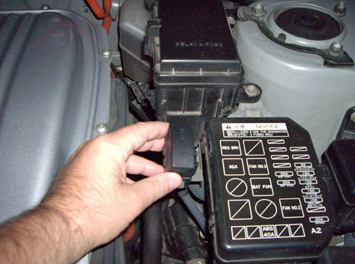
The first option with index “1” is a regular plastic box. As a rule, it has the name “Diagnostic” on it. In this model, self-diagnosis displays error codes through the “Check” light, which is located on the instrument panel, right in front of the driver’s eyes.
On more modern cars, instead of a regular light bulb there is an image of the power unit - so that you don’t get confused, they are practically the same thing. All of the above information applies only to gasoline car models.
Diesel models, instead of a light bulb and an engine icon, use a glow plug control light - in general, an image of a spiral.
The automobile manufacturer Toyota uses only two types of codes in its technology. Let's look at each of them. The first is type 09. This option is a two-digit code, where its main parameters have the following values:
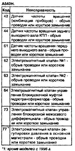
The second type is a single-digit code, where the number of pulses is equal to the fault code. The following values are important here:
Toyota Corolla: engine and automatic transmission diagnostics
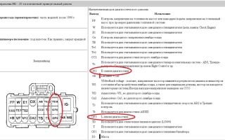
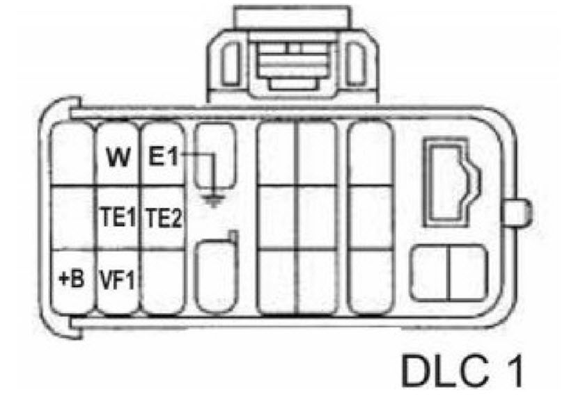
If you are not sure that you have closed the contacts correctly, you can check them. Let's start with "E1".
You need to take a low-power light bulb, connect one wire to the car body, and with the other touch all the wires in the connectors in turn, then when you find “TE1”, the light on the dashboard will start flashing.
In this simple way you can find the diagnostic output of almost any car, and you will be sure that you will not burn anything.
To diagnose the SRS, you need to close “TC” - “E1” under the hood, or “TC” - “CG” in the car’s interior, after which you can begin the diagnosis.
To read the error code when diagnosing the 4WS system, you must close TC“-“E1”. All inputs will be placed in the pictures below. With the help of them you can easily figure out where, what to close and what to insert where.
Source: http://avtognostika.ru/toyota/rasshifrovka-kodov-oshibok-toyota
Self-diagnosis Toyota Corolla: error codes
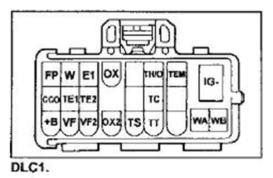
DLS 1 is a rectangular plastic box located under the hood of the car on the left.
Manual Diagnostic Check. No OBD sensor needed
Our craftsmen toyota corolla 2008 obd pccar forum went the hard way and made a wonderful miracle software called ECU. At the moment there are two current models of this program that allow you to get as deep as possible into the depths of the automotive brains, but I personally have not tested it, since the necessary parameters I have them in Torque - the pictures are on the right. Most of the parameters that are taken at the service station will also be available to you.
For example, the first of these systems works with components of the 1ZR engine, which appeared on cars with a body, and was later retained on later models.
The first character of this code is called the Alpha pointer and indicates the system in which the fault occurred: There can be an order of faults
Naturally, each mechanism is characterized by certain malfunctions that appear under certain circumstances.
An interesting fact is that they cannot always be recognized, therefore, to identify problems, owners of Toyota Corolla from the body, including the EE station wagon, have the opportunity to conduct self-diagnosis.
It is carried out using diagnostic connectors, which are usually referred to as DLC in English.
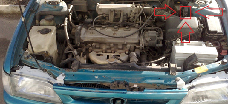
These adapters are located in three places on the machine. DLC1 is located in the engine compartment in the upper right corner, DLC2 is located in the passenger compartment under the dashboard and steering wheel.
The difference between the first and the second lies in the configuration, since diagnostics will require special equipment. In addition, through DLC1 you can check the condition of parts while the engine is running, while DLC2 is best used with the engine running. In addition, there is a DLC3 connector, which is located under the front door on the driver's side.
It can be found on cars with a robotic gearbox. It is important to note that Toyota Corolla diagnostic connectors may be located in slightly different places depending on the body type and, accordingly, the year of manufacture.
For example, on a model produced before - the DLC1 is located closer to the engine, and its location under the hood can be found significantly lower than in the version that appeared on the Russian market in 2016.
Reading information Obtaining data about the presence of faults is carried out by reading information. This procedure is carried out using one of two methods. The first involves closing the necessary terminals of the diagnostic connector using a wire or an ordinary paper clip.
After this simple procedure, you need to turn off the ignition and then just look at what signals the instrument lights are giving.
In the first case, self-diagnosis is performed by shorting the corresponding terminals of the DLC connectors with a wire or using a regular straightened paper clip. On the back of the cover there is a pin marking diagram. After this, you should turn on the car’s ignition and observe the blinking of the corresponding lights on the instrument panel.
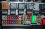
Special diagnostic devices can also be used for diagnostics: Some service stations have special diagnostic computers.
Product(s) in search results
These devices are expensive, but in addition to full diagnostics, they allow programming of various systems and reading signals coming from various nodes in real time.
Types of two-digit codes For self-diagnosis of cars, two types of two-digit codes are most often used: You can determine which type your car supports and whether there are any recorded errors in its operation as follows: For those who are not in the know: Torque allows you to turn your Android smartphone into an iPhone, too, in my opinion There is a fully functional on-board computer without the need to contact super-professional electricians, as would have to be done, for example, in the case of purchasing any multitronic.
And it’s convenient to mount it - you put your mobile phone in a smartphone holder on the dashboard, and you get data from such a fun gadget that costs no more than rubles. It displays hundreds of machine parameters in real time, creates graphs, and you can carry out easy diagnostics with it at any convenient time.
Other articles
Most of the parameters that are taken at the service station will also be available to you.
You won’t be able to carry out serious diagnostics, but I think few people need to get into the very guts of the car, when it’s enough to look at the average fuel consumption, speed, tachometer speed, coolant temperature, engine temperature, etc. of parameters in real time. Plus system errors, for which many go to service stations.
Let me warn you right away - there are two types of Japanese cars:
Position of OBD Connector in Corolla 2011, 2012, 2013
Source: http://malacolog.ru/toyota/toyota-corolla-2008-obd.html
Self-Diagnostics (error codes) – Toyota Opa Fans Club
Thanked: 12 times
ENGINE
Self-diagnosis codes are read by the number of flashes of the “CHECK ENGINE” indicator when the “TC”-“CG” terminals of the DLC3 connector under the dashboard are closed and the ignition is on.
12 – Crankshaft position sensor (P0335)
13 – Crankshaft position sensor (P0335, P1335)
14 – Ignition system, coil No. 1 (P1300) and No. 4 (P1315)
15 – Ignition system, coil No. 2 (P1305) and No. 3 (P1310)
16 – Automatic transmission control system
18 – VVT-i system – phases (P1346)
19 – Accelerator pedal position sensor (P1120)
19 – Accelerator pedal position sensor (P1121)
21 – Oxygen sensor (P0135)
22 – Coolant temperature sensor (P0115)
24 – Intake air temperature sensor (P0110)
58 – SCV drive (D-4) (P1415, P1416, P1653)
59 – VVT-i signal (P1349)
71 – EGR system (P0401, P0403)
78 – injection pump (D-4)
89 – ETCS Actuator (P1125, P1126, P1127, P1128, P1129, P1633)
92 – Cold start injector (D-4) (P1210)
97 – Injectors (D-4) (P1215)
98 – Vacuum sensor in the vacuum brake booster (C1200)
Automatic transmission
Self-diagnosis codes are read by the number of flashes of the “O/D OFF” indicator when the “TC”-“CG” (13-4) terminals of the DLC3 connector under the instrument panel are closed and the ignition is turned on (in this case, overdrive must be allowed - “O/D OFF” is not lit).
11 – Normal
37 – Automatic transmission input shaft speed
38 – Automatic transmission fluid temperature sensor
42 – Speed sensor (or output shaft speed sensor) (P0500)
44 – Speed sensor (or rear output shaft speed sensor)
46 – Accumulator pressure control solenoid (P1765)
61 – Speed sensor (or front output shaft speed sensor)
62 – Solenoid No. 1 (P0753)
63 – Solenoid No. 2 (P0758)
64 – Torque converter lock-up clutch solenoid (P0773)
67 – Automatic transmission input shaft speed sensor
68 – Torque converter lockup clutch control solenoid
– After 4 seconds, read the code by the number of indicator flashes.
– Remove the jumper from terminals “TC” and “CG”.
Reset codes (models with DLC3 connector)
– Jumper the terminals “TC” (13) and “CG” (4) of the DLC3 connector.
– Turn on the ignition.
– Press the brake pedal eight or more times within an interval of three seconds.
– The indicator should display the norm code (flashing 2 times per second).
– Remove the jumper from terminals “TC” and “CG”.
11 – Solenoid valve relay (open circuit)
12 – Solenoid valve relay (short circuit in the circuit)
13 – Electric pump relay (open circuit)
14 – Electric pump relay (short circuit in the circuit)
21 – Solenoid valve, lane. right wheels (break or short circuit)
22 – Solenoid valve, lane. a lion. wheels (break or short circuit)
23 – Rear solenoid valve right (left) wheels (break or short circuit)
24 – Rear left solenoid valve. (right) wheels (break or short circuit)
31 – AC speed sensor. right wheels (malfunction)
32 – AC speed sensor a lion. wheels (malfunction)
33 – Rear speed sensor right wheels (malfunction)
34 – Rear speed sensor a lion. wheels (malfunction)
41 – Battery voltage too high or too low
43 – Deceleration sensor (circuit fault)
44 – Deceleration sensor (open or short circuit)
49 – Brake light switch (open circuit)
51 – Electric pump power supply circuit (short circuit or open circuit)
71 – AC speed sensor right wheels (low signal)
72 – AC speed sensor. a lion. wheels (low signal)
73 – Rear speed right wheels (low signal)
74 – Rear speed sensor a lion. wheels (low signal)
75 – AC speed sensor. right wheels (incorrect signal change)
76 – AC speed sensor. a lion. wheels (incorrect signal change)
77 – Rear speed sensor right wheels (incorrect signal change)
78 – Rear speed sensor a lion. wheels (incorrect signal change)
79 – Deceleration sensor (fault)
About SRS
Self-diagnosis codes are read similarly to others, by the number of flashes of the “SRS” indicator when the “TC”-“CG” (13-4) terminals of the DLC3 connector under the dashboard are closed and the ignition is on.
Codes should be erased when the ignition is turned off. If codes are stored, a clearing procedure must be performed:
– connect two wires to terminals “TC” and “AB”
– turn on the ignition and wait at least 6 seconds
– alternately, once a second, short the “TC” and “AB” terminals to ground (the pause between short circuits is less than 0.2 seconds)
– after the third short circuit of the “TC” output, the indicator should blink at a high frequency - this means the codes are erased.
11 – Ignitor of the driver’s safety switch (short to ground)
12 – Ignitor of the driver's power supply (short to power)
13 – Igniter of the driver's power supply (short circuit)
14 – Driver’s igniter (open circuit)
15 – Front right SRS sensor (short circuit or open circuit)
15 – Front right SRS sensor (short to ground or power)
16 – Front left SRS sensor (short or open circuit)
16 – Front left SRS sensor (short to ground or power)
31 – SRS control unit malfunction
51 – Passenger igniter (short to ground)
52 – Passenger igniter (short to power)
53 – Passenger igniter (short circuit)
54 – Passenger igniter (open circuit)
- Search and sell cars at the auto market autoria.biz – buy or sell a car
- sPARK – TOYOTA rear view camera (Toyota), methods of installing cameras on Toyota
- Auction for the supply of Toyota Venza 2.7 Prestige AWD or equivalent vehicles
- car radios, gps navigators, dvd, sound, video, navigator, TV, car audio, amplifier,
- Automatic Transmission Repair TOYOTA Automatic Gear Shift
- Toyota repair in St. Petersburg » Repair of Japanese cars Toyota, Nissan, Mazda, Lexus,
- News Chronicle of road accidents in the Krasnodar region for April 6 – 8, 2012
Source: http://toyota2blog.ru/page/samodiagnostika-kody-oshibok-klub-ljubitelej
MP-Lab. Toyota car error codes. Toyota self-diagnosis codes
Toyota automatic transmission DTC codes
Toyota automatic transmission self-diagnosis codes are read by the number of flashes of the “O/D OFF” indicator when the “TE1”-“E1” terminals of the DLC1 connector under the hood or “TC”-“CG” of the OBD II – DLC3 connector under the instrument panel in the car interior are closed. with the ignition on (in this case, the inclusion of an overdrive must be allowed - the “O/D OFF” indicator does not light up).
11 – Normal 37 – Automatic transmission input shaft speed sensor (P1705) 38 – Automatic transmission fluid temperature sensor 42 – Speed sensor (or output shaft speed sensor) (P0500) 44 – Speed sensor (or rear output shaft speed sensor) 46 – Accumulator pressure control solenoid (P1765) 61 – Speed sensor (or front output shaft speed sensor) 62 – Solenoid No. 1 (P0753) 63 – Solenoid No. 2 (P0758) 64 – Torque converter lockup clutch solenoid (P0773) 67 – Frequency sensor rotation of the input shaft of the automatic transmission 68 – Torque converter lock-up clutch control solenoid
73 – Center differential lock clutch solenoid
Toyota SRS AIRBAG System DTC Codes
Self-diagnosis codes SRS AIRBAG system are deciphered by the number of flashes of the “SRS” indicator when the “TC”-“E1” terminals of the DLC1 connector under the hood or “TC”-“CG” of the DLC3 connector under the instrument panel are closed and the ignition is on.
Codes should be erased when the ignition is turned off - if erasing does not occur, you can do the following:
– connect two wires to the “TC” and “AB” terminals – turn on the ignition and wait at least 6 seconds – alternately, once a second, short the “TC” and “AB” terminals to ground (the pause between short circuits is less than 0.2 seconds) - after the third short circuit of the “TC” output, the indicator should blink at a high frequency - this means the codes are erased.
11 – Driver air protection igniter (short to ground) 12 – Driver air protection igniter (short to power) 13 – Driver air protection igniter (short circuit) 14 – Driver air protection igniter (open circuit) 15 – Front right SRS sensor (short or open) in the circuit) 15 – Front right SRS sensor (short to ground or power) 16 – Front left SRS sensor (short or open circuit) 16 – Front left SRS sensor (short to ground or power) 31 – Malfunction of the SRS control unit 51 – Passenger's airbag igniter (short to ground) 52 – Passenger's airbag igniter (short to power) 53 – Passenger's airbag igniter (short circuit) 54 – Passenger's airbag igniter (open circuit) 61 – Driver's belt pretensioner igniter (short to ground) 62 – Driver belt pretensioner igniter (short to power) 63 – Driver belt pretensioner igniter (short circuit) 64 – Driver belt pretensioner igniter (open circuit) 71 – Passenger belt pretensioner igniter (short to ground) 72 – Passenger belt pretensioner igniter (short to ground) short to power) 73 – Passenger belt pretensioner igniter (short circuit) 74 – Passenger belt pretensioner igniter (open circuit)
Toyota ABS System DTC Codes.
11 Open circuit in the solenoid valve relay circuit 12 Short circuit in the solenoid valve relay circuit 13 Open circuit in the electric pump relay circuit 14 Short circuit in the electric pump relay circuit 21 Open circuit or short circuit in the front right wheel solenoid valve 22 Open circuit or short circuit in the electric valve m valve of the front left wheel 23 Open circuit or short circuit in the solenoid valve of the rear right (left) wheel 24 Open circuit or short circuit in the solenoid valve of the rear left (right) wheel 31 Malfunction of the front right wheel speed sensor 32 Malfunction of the speed sensor front left wheel 33 Malfunction of the rear right wheel speed sensor 34 Malfunction of the rear left wheel speed sensor 41 Too high or too low battery voltage 43 Malfunction in the deceleration sensor circuit 44 Open or short circuit in the deceleration sensor circuit 49 Open in the brake switch circuit signals 51 Short circuit or open circuit of the electric pump power supply 71 Low signal level from the front right wheel speed sensor 72 Low signal level from the front left wheel speed sensor 73 Low signal level from the rear right wheel speed sensor 74 Low signal level from the speed sensor rear left wheel 75 Incorrect signal change from the front right wheel speed sensor 76 Incorrect signal change from the front left wheel speed sensor 77 Incorrect signal change from the rear right wheel speed sensor 78 Incorrect signal change from the rear left wheel speed sensor 79 Sensor malfunction slowdown
Reading ABS codes (models with DLC1 )
– Turn on the ignition. – Jumper the terminals “TC” and “E1” of the DLC1 connector. – Remove the jumper from the “WA” and “WB” pins of the DLC1 connector. – After 4 seconds, read the code by the number of indicator flashes. – Remove the jumper from pins “TC” and “E1”. – Place a jumper on pins “WA” and “WB”.
Resetting ABS (models with DLC1 )
– Turn on the ignition. – Jumper the terminals “TC” and “E1” of the DLC1 connector (the car is stationary). – Press the brake pedal eight or more times within an interval of three seconds. – The indicator should display the norm code (flashing 2 times per second). – Turn off the ignition. – Remove the jumper from pins “TC” and “E1”. – Make sure the ABS indicator goes out.
Reading ABS codes (models with DLC3 – OBD II 16 pin connector)
– Jumper the “TC” and “CG” terminals of the DLC3 connector. – Turn on the ignition. – After 4 seconds, read the code by the number of indicator flashes. – Remove the jumper from terminals “TC” and “CG”.
Resetting ABS (models with DLC3 – OBD II 16 pin connector)
– Jumper the “TC” and “CG” terminals of the DLC3 connector. – Turn on the ignition. – Press the brake pedal eight or more times within an interval of three seconds. – The indicator should display the norm code (flashing 2 times per second).
– Remove the jumper from terminals “TC” and “CG”.
We repair electronic control units for Toyota, Audi, Bmw, Volkswagen, Ford, Mercedes, Nissan, Mitsubishi, Mazda, Chevrolet, Subaru, Honda, Acura, Mini, Peugeot, Renault, Citroen, Hyundai, Kia, Daihatsu, Rover.
Source: http://car-work.ru/toyota_trouble_codes.htm
Error codes Toyota Corolla Fielder Runx Allex EUR
Fault error codes and their interpretation in Russian for Toyota Corolla Fielder Runx Allex from 2000-2006
Electric power steering
Self-diagnosis (how to read fault codes) 1. Check the “P/S” indicator. Turn on the ignition and make sure that the indicator lights up and goes out after 2 seconds. 2. Reading fault codes (without using a scanner).
a) Jumper the terminals “TC” and “CG” of the DLC3 connector.
b) Turn on the ignition. c) Read the fault codes by the number of flashes of the “P/S” indicator. Notes:
– If there are no faults, the indicator blinks continuously at a frequency of 2 times per second.
– If there is a malfunction, after a pause of 4 seconds, the output of codes begins. – The indicator flashes 1 time per second. The first sequence of flashes corresponds to the first number of the diagnostic code, consisting of two numbers. After a pause of 1.5 seconds, a second sequence of flashes is displayed, corresponding to the second number of the code. – If there are two or more fault codes, the output interval between them is set to 2.5 seconds. The display will start from the lowest number and continue upward. – After a pause of 4 seconds, the codes are displayed again.
3. Erasing fault codes (without using a scanner). a) Jumper the “TS” and “CG” pins of the DLC3 connector. b) Turn on the ignition. c) Within 8 seconds, disconnect and connect the jumper to the “CG” terminal at least 4 times. d) Make sure that the normal code is displayed.
e) Remove the jumper.
4. Check in test mode (without using a scanner). a) Jumper the “TS” and “CG” pins of the DLC3 connector. b) Turn on the ignition. c) Make sure that the normal code is displayed or read the fault codes. d) Remove the jumper. e) Turn the ignition off and on. Note: Codes 71 and 73 will be displayed in test mode even if the sensors are working.
Zero point calibration
Installation is performed in the following cases: – When removing the steering column or steering rack assembly. – When replacing the EUR control unit. 1. Set the steering wheel and front wheels to the straight ahead position. 2. Perform zero point initialization.
Note: when replacing the EUR control unit, this operation is not performed.
When using a scanner a) Stop the car (the front wheels are in the straight-ahead position).
b) Connect the scanner to the DLC3 connector and initialize.
Without using a scanner a) Stop the car. b) Jumper the “TS” and “CG” pins of the DLC3 connector. c) Jumper the “TC” and “CG” pins of the DLC3 connector. d) Within 20 seconds, disconnect and connect the jumper to the “TC” terminal 20 times. e) Turn off the ignition.
h) Perform zero point calibration.
When using a scanner
Note: Do not turn the steering wheel
a) Stop the car (the front wheels are in the straight-ahead position). b) Perform zero point calibration.
c) After calibration is completed, the “P/S” indicator should blink at a frequency of 2 times per second.
Without using a scanner a) Jumper the “TS” and “CG” terminals of the DLC3 connector and turn on the ignition. b) After 8-13 seconds, the “P/S” indicator should start flashing at a frequency of 2 times per second. c) Remove the jumper.
d) Make sure there are no fault codes.
Table of diagnostic trouble codes for the power steering system
| SAE Code/Code | System | Possible fault location |
| S1511/11 | Torque sensor (1) – malfunction |
|
| S1512/12 | Torque sensor (2) – malfunction |
|
| S1513/13 | Torque sensor (3) – malfunction |
|
| S1514/14 | Torque sensor - malfunction in the power circuit |
|
| S1515/15 | Torque sensor – zero point calibration not performed |
|
| S1516/16 | Torque sensor - zero point calibration not completed |
|
| S1521/21 | Electric motor – malfunction (current higher than permissible) |
|
| S1523/23 | Electric motor - malfunction (current deviations) |
|
| S1524/24 | Electric motor – malfunction (incorrect voltage at motor terminals) |
|
| S1531/31 | EUR control unit - malfunction (control module) | |
| S1532/32 | EUR control unit - malfunction | |
| S1533/33 | EUR control unit – malfunction (control unit board temperature sensor) | |
| S1541/41 | Speed sensor - malfunction |
|
| S1542/42 | Speed sensor - malfunction |
|
| C1544/44 | Engine speed signal - malfunction |
|
| C1545/45 | Engine speed signal - malfunction |
|
| C1551/51 | Power Supply - Circuit Fault |
|
| C1552/52 | Power supply voltage of the EUR control unit |
|
| C1554/54 | Power Supply Relay - Circuit Fault |
|
| C1555/55 | Motor Relay - Circuit Failure |
|
Source: http://kodyoshibok.ru/publ/toyota/kody_oshibok_toyota_corolla_fielder_runx_allex_ehur/7-1-0-118
How to decipher error codes on Toyota?
Self-diagnosis allows the car owner to independently detect and correct the breakdown. Of course, if the motorist has the necessary knowledge to conduct a vehicle inspection. If you have never encountered the need for self-diagnosis, then our website will help you figure it out and correctly carry out the work to check your Toyota.
Toyota Corolla 2014
Toyota cars are equipped with two connectors for self-diagnosis. They are called "DLC 1" and "DLC 2" and stand for "Data Link Connector".
“DLC 1” is visually a rectangular plastic box, which in most models is located under the hood on the left side.
You can identify the first self-diagnosis connector by the inscription “Diagnostic” on the connector cover.
As for the faulty operation of the automatic transmission, the driver will learn about breakdowns in the operation of the unit through the illuminated “OD” lamp. Accordingly, to identify malfunctions in the ABS, SRS and TRC systems, there are also corresponding lamps on the instrument panel.
Check Engine Light - lights up when a Toyota malfunction occurs.
The second connector for self-diagnosis in almost all Toyota models is located on the driver's side under the dashboard.
It has a slightly different configuration, since using this connector, special additional equipment for diagnostics is connected to the transport.
It is worth noting that this connector, although located in an inconvenient place, allows you to check the car while driving.
If you are the owner of an older Toyota model, then you need to look for the diagnostic connector in the engine compartment. These connectors are round in shape and marked in yellow and are located near the battery. In this case, there are simply no connectors located in the car interior.
Loading …
To independently check a Toyota, you can use two types of fault combinations. The first is called type 09. The combination is a two-digit code with certain characteristics:
- the pulse width is a fraction of a second;
- pause between impulses also;
- the pause between units and tens is one and a half seconds;
- the pause between fault displays is 2.5 seconds;
- the pause between series of breakdown combinations is 4.5 seconds.
Diagnostic connector for checking the machine
As for the second type of fault combinations, it is called type 10. It is a single-digit code, where the number of pulses corresponds to the fault combination. Its characteristics are:
- pulse width is approximately half a second;
- half a second pause between pulses;
- the pause between displayed combinations is 2.5 seconds;
- the pause between series of error combinations is 4.5 seconds.
Step-by-step diagnostics
To carry out self-diagnosis of the internal combustion engine or transmission system, do the following:
- First, you need to open the hood of the vehicle and find a plastic block that says “Diagnostic” on it.
- Then unscrew or remove the cover and look at the back of it. The terminals must be marked on it. Now take a piece of wire or wire (a regular paper clip will do) and short-circuit the terminals “TE1” and “E1”.
- Next, you need to get behind the wheel and turn on the ignition.
Please note that the stove and air conditioner must be turned off at this time. You need to keep an eye on the lights on your dashboard. When you turn the key in the ignition, the OD and Check Engine lights will start blinking. If the lamps blink for a long time and without interruptions, that is, with a flash and a pause of a fraction of a second more than eleven times, then the control unit reports that no malfunctions have been detected in the operation of the internal combustion engine or automatic transmission. In this case, you can pull out the jumper and drive on with peace of mind. If the Check Engine light blinks many times with an interval of 4.5 seconds, then your Toyota uses code type 10. Multiple blinks indicate that no faults have been detected in the on-board computer memory. - If the lamp begins to detect errors, then you will know about it by its blinking. We recommend that you take a piece of paper with a pen and write down all the combinations, since you will have to decipher them later.
Scheme diagnostic connector DLC2
Advice: if you are not sure that you have made the correct contacts, then do the following.
Turn on the ignition and take a test lamp with wires, connect one of them to ground, that is, to the Toyota body, and connect the other wire in turn to each connector for self-diagnosis. When you find “TE1”, the Check Engine light will start blinking.
Of course, this operation should be performed with an assistant, since it will not be particularly convenient for you to diagnose the connectors under the hood and at the same time monitor the dashboard.
This instruction is relevant for all Toyota cars. This completes the self-diagnosis. Now you only need to decipher the received error codes, which we will discuss further.
Decoding combinations
Gasoline internal combustion engines
First, let's look at deciphering the combinations of self-diagnosis faults inherent to Toyota gasoline engines.
Diagnostic connector DLC1
| Combination | Decoding |
| 12, 14 | The control unit informs the car owner about the incorrect operation of the crankshaft position control sensor. |
| 14,15 | A breakdown of one of the four ignition coils has been reported. |
| 16 | Incorrect operation of the transmission has been registered. It is recommended to carry out a more thorough check of the gearbox. |
| 19 | Incorrect accelerator pedal position. It could also be a problem with the pedal position sensor. |
| 21 | The oxygen sensor has failed.
For correct operation, it is recommended to replace the device. |
| 22 | The refrigerant temperature control device in the refrigeration system sends an incorrect signal to the BC. The sensor needs to be replaced. |
| 24 | The intake air temperature control sensor is broken. |
| 25 | The oxygen sensor sends an incorrect signal to the on-board computer. In particular, the BC recorded a signal that the mixture in the injection system was too lean. |
| 31 | The control unit reports incorrect operation of the absolute pressure control device in the internal combustion engine system. |
| 34 | Malfunctions in the functioning of the turbocharging system have been reported. |
| 36 | The CPS sensor has failed. |
| 41 | The on-board computer reports an incorrect signal coming from the throttle position control device. |
| 42 | The driver is notified of a breakdown of the vehicle speed sensor. |
| 43 | The on-board computer receives an incorrect signal from the starter. A thorough check of the mechanism should be carried out. |
| 49 | Incorrect operation of the fuel pressure monitoring device.
It is necessary to replace the sensor and check again. |
| 52, 53, 55 | Incorrect operation of one of the knock sensors. The device should be replaced. |
| 92 | Incorrect operation of the cold start injector. The element must be replaced. |
| 98 | A breakdown of the vacuum control device in the vacuum brake booster was registered. |
Diesel internal combustion engines
Checking the car for errors using special diagnostic equipment
Next, let's look at deciphering the errors that occur when diagnosing Toyota cars with diesel engines.
| Combination | Decoding |
| 12 | A broken crankshaft sensor has been reported. |
| 13 | The control unit has detected a breakdown in the operation of the shaft speed control device. |
| 14 | A breakdown in the operation of the injection timing adjustment valve was detected. |
| 15 | Indicates that the throttle servo is not operating properly. |
| 17 | There are problems with the control unit. It is necessary to make a more accurate diagnosis of the block. |
| 18 | Problems have been detected in the operation of the electromagnetic bypass valve. The device should be replaced and diagnostics performed again. |
| 19 | The clutch pedal position control device does not work correctly. Replace the sensor. |
| 22 | The antifreeze temperature control mechanism in the cooling system has failed. |
| 24 | The intake air temperature sensor has failed. |
| 32 | The on-board computer registered a malfunction in the functioning of the correction resistors. |
| 35 | Malfunction of the boost pressure control device. Replace the sensor and re-diagnose the vehicle. |
| 39 | Incorrect operation of the fuel temperature sensor. |
| 42 | The vehicle speed sensor has stopped working. The device must be replaced. |
| 96 | There is a malfunction in the EGR valve position sensor. |
Automatic transmission
Diagnostic connector for checking the machine
| Combination | Decoding |
| 11 | This combination means that no malfunctions have been identified in the operation of the automatic transmission system. |
| 37 | A malfunction of the unit input shaft speed control device has been reported. |
| 38 | Indicates a failure of the transmission fluid temperature sensor.
To prevent damage to the unit, you should replace the sensor, and then do the diagnostics again. |
| 42, 44 | There has been a malfunction in the output shaft speed sensor. It is recommended to replace the device for correct operation of the unit. |
| 46 | The hydraulic accumulator pressure control solenoid has failed. |
| 61 | There is a malfunction in the speed sensor. The device should be replaced. |
| 62, 63 | The first or second solenoid has failed. |
| 64 | The control unit informs the car owner about the incorrect operation of the torque converter lock-up clutch solenoid. |
| 73 | The on-board computer detected incorrect operation of the center differential lock clutch solenoid. |
Other codes
Scanner for checking a car for errors
Next, let's look at the error codes that appear when diagnosing a Toyota using special equipment. The list of errors is far from complete, but the most common malfunctions are considered.
| Combination | Decoding |
| c1201 | This combination indicates that the motor is not operating correctly. in practice, such an error occurs if the engine speed drops below 500. |
| p0171 | The combination indicates that the fuel mixture level in the engine is too lean. |
| p1604 | The car's on-board computer reports a breakdown of the intake system. A detailed check of the system should be carried out. |
| p1656 | An open or short circuit has been reported in the VVT system. Also, the on-board computer could record a breakdown in the operation of the VVT valve or electronic control unit. |
| b1801 | This code indicates an open circuit in the squib circuit on the driver's seat side. The wiring should be checked for shorts and breaks. |
| p1349 | Indicates incorrect operation of the VVT-i valve. The device must be replaced. |
| c1241 | The on-board computer reports that the pressure limit switch in the ABS unit is closed. The circuit should be checked for breaks and short circuits. |
| p0352 | Malfunctions were detected in the operation of the ignition system circuit. To ensure proper operation of the transport, check the circuit more accurately. |
| p0051 | The oxygen sensor heating device has failed. |
| b0101 | The control unit reports incorrect operation of the security system, in particular the airbags. |
Video from Dmitry Kuzmin “Toyota Karina E paper clip self-diagnosis”
Source: http://AvtoZam.com/toyota/kody-oshibok-avto/